


Rev. B
Reelmaster 5010 Series Page 5 -- 27 Electrical System
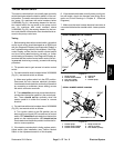
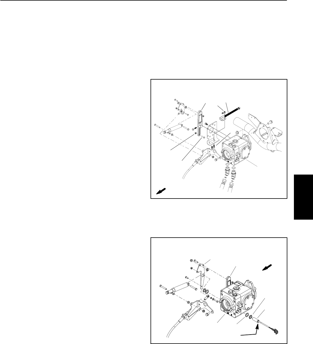
Traction Neutral Switch
The traction neutral switch is a normally open proximity
switch that closes when the traction pedal is in the neu-
tral position.The switch mountsto a bracketon the trac-
tion pump. On machines with serial numbers below
310000000 (Fig. 31), the sensing element for the trac-
tion neutral switch is a cap screw on the pump control
arm. On machines with serial numbers above
310000000 (Fig. 32), the sensing element for the trac-
tion neutralswitch is thetraction lever bracketthat is se-
cured to the pump control arm.
Testing
1. Before testing the traction neutral switch, the switch
and its circuit wiring should be tested as an ECM input
with the Diagnostic Display (see Diagnostic Display in
the Troubleshooting section of thischapter). If the Diag-
nostic Display verifies that the traction neutral switch
and circuit wiring are functioning correctly, no further
switchtesting isnecessary.Ifthe DiagnosticDisplayde-
termines that the traction neutral switch and circuit wir-
ing are not functioning correctly, proceed with testing
procedure.
2. Tilt operator seat to gain access to traction neutral
switch.
3. On machines with serial numbers below310000000
(Fig. 31), test neutral switch as follows:
A. Make sure ignition switch is in the OFF position.
Disconnect the wire harness electrical connector
fromthe switchand checkthecontinuityoftheswitch
by connecting a multimeter (ohms setting) across
the switch connector terminals.
B. Thereshould becontinuityacross theswitchter-
minals when the traction pedal is in the neutral posi-
tion. There should not be continuity when the
traction pedal is in either the forward or reverse
direction.
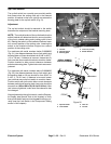
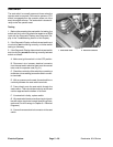
4. Onmachines with serialnumbers above310000000
(Fig. 32), test neutral switch as follows:
A. Turn ignition switch to the ON position (do not
start engine) and check LED on cable end of neutral
switch.LED shouldbe illuminatedwhen thetraction
pedal is in the neutral position. LED should not be
illuminatedwhenthetractionpedalisineitherthefor-
ward or reverse position.
5. If the traction neutral switch is faulty, replace switch.
Adjust switch after installation (see Traction Neutral
Switch in the Adjustments section of this chapter).
6. Ifthe neutral switchtests correctly anda circuitprob-
lem still exists, check wire harness (see Wiring Sche-
matic and Circuit Drawings in Chapter 9 -- Electrical
Diagrams).
7. Make sure that wire harness electrical connector is
connected to thetraction neutralswitch. Loweroperator
seat.
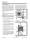
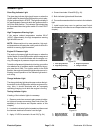
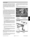
1. Screw (2 used)
2. Traction neutral switch
3. Lock nut (2 used)
4. Pump control arm
5. Cap screw
6. Jam nut
7. Traction pump
Figure 31
FRONT
2
3
4
5
1
6
7
SERIAL NUMBER BELOW 310000000
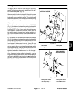
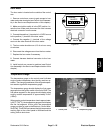
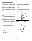
Figure 32
FRONT
1. Traction pump
2. Traction neutral switch
3. Traction lever bracket
4. Pump control arm
5. Jam nut (2 used)
6. Lock washer (2 used)
2
3
4
5
1
6
SERIAL NUMBER ABOVE 310000000
LED location
Electrical
System