


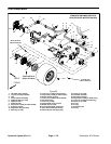

Rev. B
Reelmaster 5010 SeriesHydraulic System (Rev. C) Page 4 -- 84
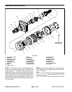
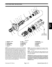
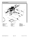
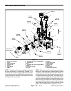
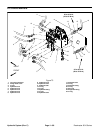
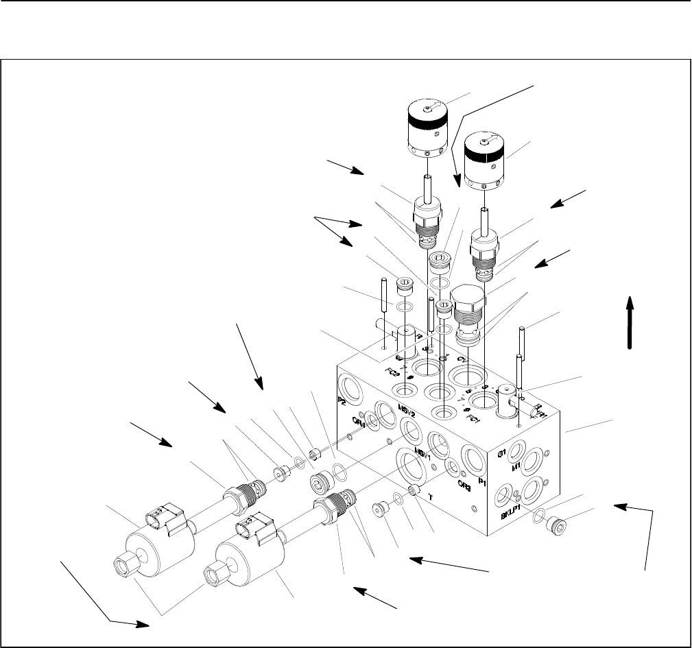
Mow Control Manifold Service
1. Mow control manifold
2. O--ring
3. Plug (zero leak #6)
4. Orifice (0.020)
5. O--ring
6. Plug (SAE #4)
7. Seal kit
8. Solenoid relief valve cartridge (MSV1)
9. Solenoid coil
10. Nut
11. Solenoid relief valve cartridge (MSV2)
12. Seal kit
13. Plug (zero leak #8)
14. O--ring
15. Seal kit
16. Flow control valve
17. Rotary handle
18. Check valve
19. Seal kit
20. Pin (4 used)
21. Rotary spool (2 used)
Figure 71
41 ft--lb
(55 N--m)
40 ft--lb
(54 N--m)
30 ft--lb
(40 N--m)
198 in--lb
(22 N--m)
40 ft--lb
(54 N--m)
198 in--lb
(22 N--m)
41 ft--lb
(55 N--m)
165 in--lb
(18.6 N--m)
25 ft--lb
(33 N--m)
48 to 60 in--lb
(5.4 to 6.7 N--m)
25 ft--lb
(33 N--m)
165 in--lb
(18.6 N--m)
UP
4
3
1
2
9
10
11
8
5
6
7
12
20
21
13
14
15
16
17
18
19
3
2
3
2
6
5
4
9
14
13
15
16
17
NOTE: The ports on the control manifolds are marked
for easy identification of components. Example: P1 on
isthe pumpP1connectionportand MSV2isthelocation
for the solenoidrelief valve MSV2 (See HydraulicSche-
matics to identify the function of the hydraulic lines and
cartridge valves at each port).
NOTE: The mow control manifold uses several zero
leak plugs. These plugs have a tapered sealing surface
on the plug head that is designed to resist vibration in-
duced plug loosening.The zero leak plugs alsohave an
O--ring to provide a secondary seal. If zero leak plug re-
moval is necessary, lightly rap the plug head using a
punch and hammer before using an allen w rench to re-
move the plug: the impact w ill allow plug removal with
less chance of damage to the socket head of the plug.
When installing plugs into the control manifold, torque
plugs to the values identified in Figures 71 and 74.