


Reelmaster 5010 Series Hydraulic System (Rev. C)Page 4 -- 9
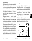
Traction Circuit
The hydraulic traction circuit consists of a variable dis-
placementpistonpump(P5) connectedinaclosedloop,
parallelcircuittotwo (2)orbitalrollervane wheelmotors.
The traction pump input shaft is rotated by a drive shaft
that is driven from the engine flywheel.
Traction circuit pressure (forward and reverse) can be
measured at test ports located in the hydraulic tubes
that connect the front wheel motors.
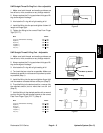
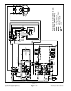
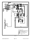
Forward Direction (Fig. 8)
Pushing the top of the traction pedal angles the traction
pump swash plate to create a flow of oil. This oil flow is
directed to the wheel motors via hydraulic hoses and
tubes to drive the wheels in the forward direction. For-
ward traction pressure is limited to 3625 PSI (250 bar)
by the forward traction relief valve (R3) located in the
traction pump.
Oil flowing fromthe wheel motors returnsto the variable
displacement pump and is continuously pumped
through the traction circuit as long as the traction pedal
is pushed.
The angleof the swashplate determinespump flow and
ultimately traction speed.When the traction pedal isde-
pressedasmallamount, asmallswashplaterotation re-
sultsinlowpumpoutputandlowertractionspeed.When
the traction pedal is depressed fully, the pump swash
plate rotates fullyto provide maximum pump output and
traction speed.
Gear pumpsection (P3)supplies oilflow forthe steering
circuit and also provides a constant supply of charge oil
to the closed loop traction circuit. This charge oil pro-
videslubricationfortractioncircuitcomponentsandalso
replenishes traction circuit oil that is lost due to internal
leakage in the traction circuit.
Gear pump(P3) takesits suction fromthe hydraulic res-
ervoir.Charge pump flow is directedto the low pressure
side of the closed loop traction circuit. Charge pressure
is limited by the charge relief valve (R5) located in the
traction pump.Thec harge reliefpressure is200 PSI(14
bar).
The piston pump ( P5) includes a flushing valve (R10)
that bleeds off a small amount of hydraulic fluid for cool-
ingofthe closedlooptractioncircuit.The chargesystem
replenishes oilthat isbled fromthe traction circuitby the
flushing valve.
Reverse Direction
The traction circuit operates essentially the same in re-
verse as it does in the forward direction. However, the
flow through the circuit is reversed. Pushing the bottom
of the traction pedal rotates the traction pump swash
plate to create a flow of o il. This oil is directed to the
wheel motors to drive the wheels in the reverse direc-
tion. Reverse traction pressure is limited to 3625 PSI
(250bar)bythe reversetractionreliefvalve (R4)located
in the traction pump.
Oil flowing from the wheel motors returns to the traction
pump and is continuously pumped through the closed
loop traction circuit as long as the traction pedal is
pushed.
The charge circuit and flushing valve (R10) function the
same in reverse as they do in the forward direction.
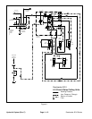
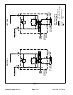
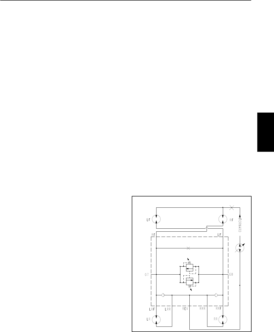
CrossTrax
TM
AWD (Optional)
On machines equipped with the optional CrossTrax
TM
AWD kit, four wheel motors are used (Fig. 9). Traction
pump flow is directed to the front tires and the opposite
rear tires to maximize traction. To reduce tire scuffing
when turning, traction system pressure is equalized in
the AWD manifoldwith anorifice anda bi--directional re-
lief valve. Check valves in the AWD manifold allow the
rear wheel motors to over run during tight turns.
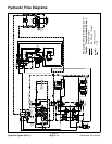
Figure 9
G5
CrossTrax AWD Hydraulic Schematic
TM
Hydraulic
System