


Rev. B
Reelmaster 5010 SeriesHydraulic System (Rev. C) Page 4 -- 106
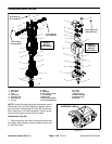
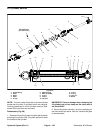
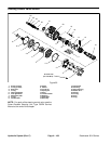
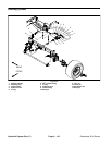
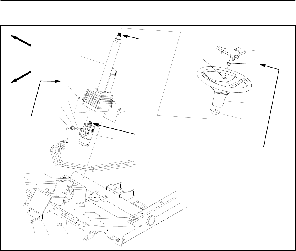
Steering Control Valve
1. Steering control valve
2. Flange head screw
3. Foam collar
4. Steering wheel
5. Flat washer
6. Lock nut
7. Steering wheel cover
8. Steering column
9. Socket head screw (4 used)
10. O--ring
11. Hydraulic fitting (4 used)
12. O--ring
13. Steering column brace
14. Flange nut
Figure 90
FRONT
RIGHT
20 to 26 ft lb
(28to35N--m)
ANTISEIZE
LUBRICANT
ANTISEIZE
LUBRICANT
4
3
1
2
9
10
11
8
5
6
7
12
2
13
14
7to10ft--lb
(9.5 to 13.5 N--m)
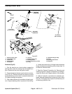
Removal (Fig. 90)
1. Park the machine on a level surface, engage the
parking brake, lower the cutting units and stop the en-
gine. Remove the key from the ignition switch.
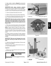
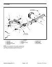
2. Remove fastenersthat secure shroud tofront of ma-
chine (Fig. 91). Remove shroud from machine to allow
accesstosteeringc ontrol valve.Locateandretrievetwo
(2) rubber bushings and spacers.
3. Slide rubber bellows up from bottom of steering col-
umn. Support steering column to prevent it from falling.
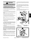
4. Loosen andremove four (4) flangehead screws and
flange nuts that secure steering column brace (item 13)
to machine. Remove brace.
5. Read the General Precautions for Removing and
Installing Hydraulic System Components at the begin-
ning of the Service and Repairs section of this chapter.
6. Label all hydraulic connections for assembly pur-
poses. Note port designations on steering control valve
(Fig. 92). Thoroughly clean hydraulic connections prior
to loosening hydraulic lines.