


Reelmaster 5010 SeriesPage 5 -- 24Electrical System
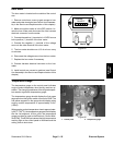
Indicator Lights
Glow Plug Indicator Light
The glow plug indicator light should come on when the
ignitionswitchisplacedin theRUNpositionpriortoplac-
ing the ignition switch in START. The light should stay lit
for approximately 6 seconds while the ignition switch is
left in the RUN position. The indicator light should also
be illuminated when the ignition switch is in the START
position.
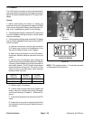
High Temperature Warning Light
If the engine coolant temperature reaches 221
o
F
(105
o
C) (approximate), the high temperature warning
light should come on.
NOTE: When machine is in mow operation, high cool-
ant temperature will cause the cutting reels to shut off in
addition to warning light illumination.
Engine Oil Pressure Light
The engine oil pressure light should come on when the
ignition switch isin the RUN position withthe engine not
running. Also, it should illuminate with the engine run-
ning if the engine oil pressure drops to an unsafe level.
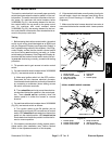
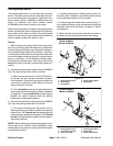
Totesttheoilpressurelightandcircuitwiring,groundthe
wire attached to oil pressure switch located on the en-
gine near the oil filter. Turn ignition switch to the RUN
position;theengine oilpressurelight shouldcomeonin-
dicating correct operation of the indicator light and cir-
cuit wiring.
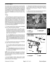
Charge Indicator Light
Thechargeindicatorlightshouldcomeonwhen theigni-
tionswitchisin theRUNpositionwiththeenginenotrun-
ning. Also, it should illuminate with an improperly
operating charging circuit while the engine is running.
Testing Indicator Lights
If testing of the indicator lights is necessary:
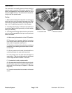
1. Remove control armcovers togain access to indica-
tor light and harness connectors (see Control Arm Dis-
assembly in the Service and Repairs section of this
chapter).
2. Locatethe indicatorlight tobetested anddisconnect
the harness electrical connector from the light.
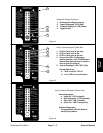
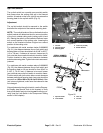
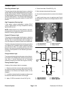
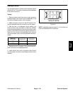
3. Apply 12 VDC to terminals 1A and 2A (Fig. 24).
4. Ground terminals 1B and 2B (Fig. 24).
5. Both indicator lights should illuminate.
6. Connectharnesselectricalconnectortotheindicator
light.
7. Install control arm cover to machine (see Control
ArmAssembly inthe Serviceand Repairssection ofthis
chapter).
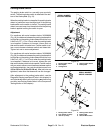
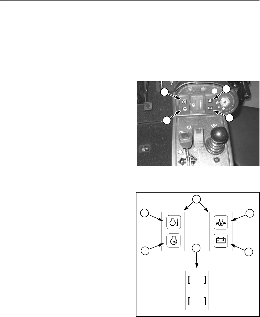
1. Glow plug indicator
2. High temp warning
3. Engine oil pressure
4. Charge indicator
Figure 23
1
4
3
2
Figure 24
1. Glow plug indicator
2. High temp warning
3. Engine oil pressure
4. Charge indicator
5. Indicator light front
6. Indicator light back
1A (+)
2A (+)2B (--)
1B (--)
1
4
3
2
6
5