


Reelmaster 5010 Series
Cutting Units (Rev. C)
Page 7 -- 38
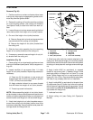
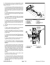
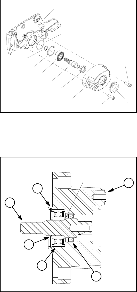
3. If drive bearing housing was disassembled, install
new components noting proper orientation as shown in
Figures 43 and 44.
A. Installbearing onshaftbypressing equallyonthe
inner and outer bearing races. Install the bearing so
that thebearing seal isclosest to theshoulder on the
shaft. Install snap ring (item 6) onto shaft to retain
bearing.
B. Installnew grease sealinto housingwith thelip of
the seal toward the drive shaftsplines. Apply grease
to lip of seal.
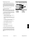
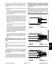
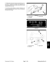
C. Fill cavity between bearing location and grease
seal 50% to 75% full with high temperature Mobil
XHP--222 grease (or equivalent).
D. Carefully slide shaft and bearing fully into pivot
hub bore taking care to not damage the greaseseal.
Install retaining ring(item 5) to secure bearing inpiv-
ot hub.
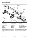
4. Assemble roller brush components using Figure 40
as a guide.
A. Apply a light coating of grease to inner diameter
of the grommet in drive bearing housing.
B. Apply Loctite #242 (or equivalent) to threads of
flangehead screw(item20)that securesdrivepulley
to drive shaft.
C. Torque flange head screw (item 20) that secures
drive pulley to drive shaft from 27 to 33 ft--lb (37 to
44 N--m).
D. Apply antiseize lubricant to square key that lo-
cates driven pulley onto roller brush shaft.
E. Torque flange nut (item 11) that secures driven
pulley to roller brush shaft from 17 to 21 ft--lb (23 to
28 N--m).
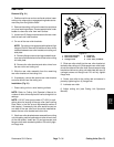
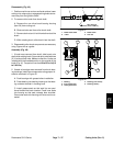
F. Check alignment of pulleys with a straight edge
placed along the outer face of the driven pulley (Fig.
45). The outer faces of the driven and drive pulleys
(not the idler pulley) should be in line within 0.030”
(.76 mm). If necessary to align pulleys, remove driv-
en pulley from brush shaft and add or remove wash-
er(s) (item 9) until drive and driven pulleys are
aligned.
G. Position excluder seals on brush shaft so that
seals just touch bearing housings.
H. To tension drive belt, make sure idler pulley lock
nut is loose. Lift up on idler plate tab with 15 lbs of
force for a new belt (10 lbs of force for a used belt)
and tighten pulley lock nut. Refer to decal on brush
plate (Fig. 46).
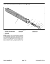
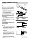
1. Bearing housing
2. Drive shaft
3. Ball bearing
4. Grease seal
5. Retaining ring
6. Snap ring
7. O--ring
8. Side plate
9. Socket head screw
10. Grommet
Figure 43
1
2
3
4
5
6
9
10
7
8
9
1. Bearing housing
2. Drive shaft
3. Ball bearing
4. Grease seal
5. Retaining ring
6. Snap ring
Figure 44
Fill cavity
50 to 75% full
with grease
2
6
3
4
1
5