


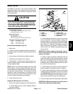


Reelmaster 5010 Series Page 5 -- 55 Electrical System
Very small changes to the oil level in the sealed hydrau-
lic reservoirresult in movementof the leakdetector’sin-
ternal float. The internal microprocessor of the
TurfDefender
TM
analyzesthe floatmovementanddeter-
mines if there is a leak in the hydraulic system or if the
change is caused by other factors (e.g. hydraulic fluid
temperature changes or lift cylinder operation). During
machine operation, if a hydraulic leak is detected, the
TurfDefender
TM
alarm will sound long, continuous
beeps and the cutting units will be shut off.
When the ignition switch is turned to RUN, the TurfDe-
fender
TM
alarm should sound a single, short beep indi-
cating normal operation. If there is no beep when the
ignition switch is turned to RUN or if the alarm gives 4
short beeps it means a system problem has been de-
tected that should be checked by a technician.
The handheld Diagnostic Display (see Special Tools in
this chapter) with the TurfDefender
TM
overlay decal
(supplied with TurfDefender
TM
kit) can be used to accu-
ratelycheckhydraulicreservoiroillevelandalsotoiden-
tify causes of TurfDefender
TM
problems. See
Troubleshooting in this chapter for information on trou-
bleshooting the TurfDefender
TM
system.
TurfDefender
TM
Service
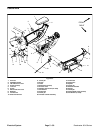
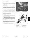
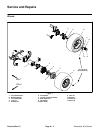
1. The solenoid valve can be removed from the upper
housing for inspection if necessary. Two (2) o--rings are
used to seal the solenoid valve to the upper housing.
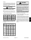
Thesolenoidcoilresistanceshouldbeapproximately69
ohms. When installing solenoid valve into upper hous-
ing, torque from 20 to 25 ft--lb (27 to 33 N--m).
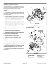
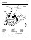
2. If the leak detector assembly is to be removed from
the hydraulic reservoir:
A. Tipthehydraulicreservoir covertogainaccess to
TurfDefender
TM
. Thoroughly clean the top of the hy-
draulic reservoir around the TurfDefender
TM
upper
housing.
B. Disconnectleak detectorwire harnessconnector
from machine wire harness. Disconnect wire har-
ness connectors from the alarm.
C. Remove six (6) socket head screws that secure
leak detector assembly to hydraulic reservoir. Lift
leak detector from reservoir. Remove and discard
gasketfrombetweenleakdetectorassemblyandhy-
draulic reservoir.
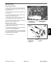
3. The main body of the TurfDefender
TM
is not service-
ableanddisassembly shouldnotbenecessary.Remov-
al of the upper housing from the leak detector housing
is not recommended.
4. Access to the internal float can be completed by re-
moving the bottom cover (item 10) and gasket (item 9).
If bottom cover is removed, carefully clean mating sur-
faces and replace gasket. Secure bottom cover with
three (3) cap screws and torque from 100 to 125 in--lb
(12to14N--m).
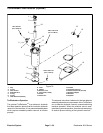
5. Toinstallleakdetectorassembly tothehydraulicres-
ervoir:
A. Position new gasket to the top of the hydraulic
reservoir. Make sure that the gasket holes align cor-
rectly with holes in hydraulic reservoir.
B. Insert leak detector into reservoir opening. Align
holes in leak detector housing, gasket and hydraulic
reservoir.
C. Secure leak detector assembly to hydraulic res-
ervoir with six (6) socket head screws. Torque
screws from 100 to 125 in--lb (12 to 14 N--m).
D. Connect leak detector wire harness connector to
machine wire harness. Correctly connect wire har-
ness leads to alarm (red/yellow harness wire to
alarm+ terminaland black/yellowwire toalarm -- ter-
minal).
E. Lower hydraulic reservoir cover and secure in
place.
Electrical
System