


Reelmaster 5010 SeriesPage 5 -- 26Electrical System
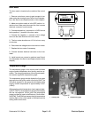
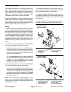
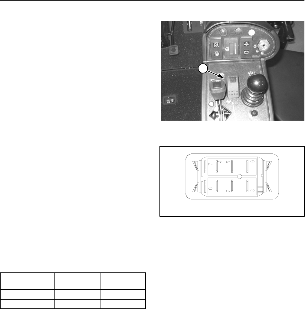
PTO Switch
The PTO switch is mounted on the control panel and is
pressedtoallowthecuttingunitstooperate.Anindicator
light on the switch identifies when the PTO switch is en-
gaged.
Testing
1. Before disconnecting the switch for testing, the
switch and its circuit wiring should be tested as an ECM
input with the Diagnostic Display (see Diagnostic Dis-
play in the Troubleshooting section of this chapter).
2. IftheDiagnostic DisplayverifiesthatPTOswitch and
circuit wiring are functioning correctly, no further switch
testing is necessary.
3. Ifthe Diagnostic Displaydeterminesthat PTOswitch
and circuit wiring are notfunctioning correctly, test PTO
switch as follows:
A. Remove control arm covers to gain access to
PTO switch (see Control Arm Disassembly in the
Service and Repairs section of this chapter).
B. Make sure ignition switch is in the OFF position.
Disconnect harness electrical connector from the
switch.
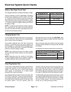
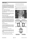
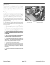
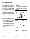
C. With the use of a multimeter (ohms setting), the
switchfunctions maybetested todetermine whether
continuity exists between the various terminals for
each switch position. The PTO switch terminals are
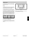
marked as shown in Figure 28. The circuitry of this
switch is shown in the chart below. Verify continuity
between switch terminals.
SWITCH
POSITION
NORMAL
CIRCUITS
OTHER
CIRCUITS
ON 2+3 5+6
OFF 2+1 5+4
D. Replace switch if necessary.
E. If switch tests c orrectly and circuit problem still
exists, check wire harness (see Wiring Schematic
and Circuit Drawings in Chapter 9 -- Electrical Dia-
grams).
F. Connect harness electrical connectorto the PTO
switch.
G. Install control arm cover to machine (see Control
Arm Assembly in the Service and Repairs section of
this chapter).
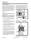
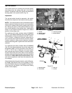
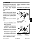
1. PTO switch
Figure 27
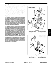
1
Figure 28
BACK OF SWITCH
NOTE: PTO switch terminals 1, 4, 5 and 6 are notused
on Reelmaster 5010 machines.