


Reelmaster 5010 Series Page 5 -- 51 Electrical System
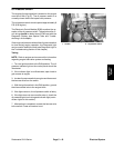
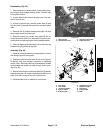
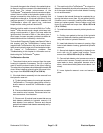
Disassembly (Fig. 63)
1. Park machine on a level surface, lower cutting units,
stop engine and engage parking brake. Remove key
from ignition switch.
2. Loosen latches and remove access cover from out-
side of control arm.
3. At front of control arm, remove screw (item 6) and
lock nut (item 5) that secure control arm covers to each
other.
4. Remove five (5) washer head screws (item 16) that
secure each cover to control arm.
5. Remove control arm covers from machine. As LH
control arm cover (item 3) is removed from control arm,
unplug wire harness connector from headlight switch.
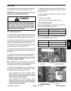
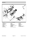
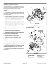
6. Remove electrical components from control arm as
needed using Figure 65 as a guide.
Assembly (Fig. 63)
1. Install all removed electrical components to control
arm using Figure 65 as a guide.
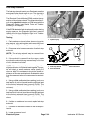
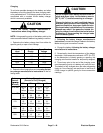
2. Position covers to control arm. As LH cover (item 3)
is placed, plug wire harness connector to headlight
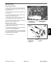
switch. Also, make sure that wire harness and throttle
control cable are routed correctly through cover open-
ings (Fig. 64).
3. Secureeachcovertocontrolarmwithfive(5)washer
headscrews(item16).Installscrew(item6)andlocknut
(item 5) to s ecure covers at front of control arm.
4. Install access cover to outside of control arm.
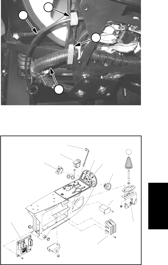
1. Wire harness
2. Harness foam seal
3. Throttle control cable
4. Cable foam seal
Figure 64
1
3
2
4
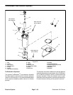
1. Fuse block
2. Hour meter
3. Joystick assembly
4. Ignition switch
5. Indicator light
6. Temperature gauge
7. Diagnostic light
8. PTO switch
9. Indicator light
10. ECM
Figure 65
2
3
1
6
7
5
4
8
9
10
Electrical
System