


Rev. A
Reelmaster 5010 SeriesHydraulic System (Rev. C) Page 4 -- 100
2. Clean all motor components with solvent. Dry all
parts with compressed air.
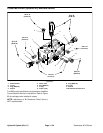
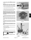
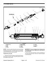
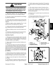
3. Inspect drive gear, idler gear and bearing blocks
(Fig. 87) for the following:
A. Gear shaftsshould be free ofr ough surfaces and
excessive wearat bushing pointsand sealing areas.
Scoring, rough surfaces or wear on gear shafts indi-
cates need for replacement.
B. Gear teeth should be free of excessive scoring
and wear. Any broken or nicked gear teeth must be
replaced.
C. Inspect gear face edge for sharpness. Sharp
edges ofgears will millinto bearing blocksand, thus,
must be replaced.
D. Bearing areas of bearing blocks should not have
excessive wear or scoring.
E. Face of bearing blocks that are in contact w ith
gears should be free of wear, roughness or scoring.
4. Inspect front flange and rear cover for damage or
wear.
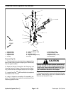
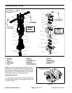
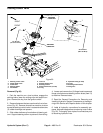
Assembly (Fig. 83)
NOTE: When assembling the motor, check the marker
line made during disassembly to make sure the parts
are properly aligned during assembly.
1. Lubricate new O--rings, pressure seals, back--up
gaskets and seal grooves with a thin coat of petroleum
jelly. Lubricate all other internal parts freely with clean
hydraulic oil.
2. Install new shaft seal(s) into front flange. Install seal
retainer.
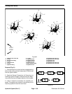
NOTE: Pressure seals and back--up rings in Sauer--
Danfoss motors fit in grooves machined into front and
rear cover (Fig. 86). Pressure seals and back--up rings
in Bosch motors fit in grooves machined into bearing
blocks.
3. Install lubricated pressure seals into the machined
grooves and follow by carefully placing the back--up
rings into the grooves.
4. Install lubricated O--rings to the body.
5. Lubricate gear faces and bearing surfaces of drive
gear, idler gear and bearing blocks with clean hydraulic
oil. Carefully assemblebearing blocks and gears noting
identification marks made during disassembly.
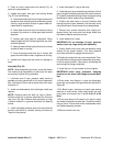
6. Position the motor body on its side. Carefully slide
bearing block and gear assembly into the body cavity
using identification marks made during disassembly.
7. Remove any excess lubrication from mating sur-
faces of body, rear cover and front flange. Make sure
that these surfaces are clean and dry.
8. Install dowel pins in body.
IMPORTANT: Do not dislodge O--rings, pressure
seals or back--up rings during final assembly.
9. Gently slide the rear cover onto the assembly using
marker line for proper location. Firm hand pressure
should be sufficient to engage the dowel pins.
10.Position themotorwithrear coverdownwards.Care-
fullyslide thefrontflangeonto theassemblyusing mark-
er line for proper location. Take care to not damage the
seal during front flange installation.
11.Install the four (4) cap screws and hand tighten.
IMPORTANT: Avoid using excessive clamping
pressure on the motor front flange to prevent dam-
age.
12.Place motor front flange in a vise and alternately
torque the cap screws to the specifications identified in
Figure 83.
13.On Bosch motor, lubricate and install new sealing
washers on relief valves. Install relief valves into rear
cover ports and torque from 11 to 15 ft --lb (15 to 20
N--m).
14.Put a small amount of hydraulic oil in port on motor
and rotate driveshaft one revolution. Protect the shaft if
using a pliers. If drive shaft binds, disassemble motor
and repeat assembly process.
15.Remove motor from vise.