


Reelmaster 5010 Series Page 6 -- 21 Chassis (Rev. C)
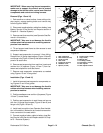
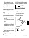
IMPORTANT: When removing the seat suspension,
make sure to support the control arm to prevent
damage to the throttle cable, control arm electrical
components and control arm wiring harness.
Removal (Figs. 15 and 16)
1. Park machine on a level surface, lower cutting units,
stop engine, engage parking brake and remove key
from the ignition switch.
2. Disconnect negative battery cable from battery (see
Battery Service in the Service and Repairs section of
Chapter 5 -- Electrical System).
3. Remove seat from machine (see Operator Seat Re-
moval in this s ection).
IMPORTANT: Take care to not damage the throttle
cableorelectricalharness whenremovingseatsus-
pension from machine.
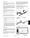
4. Tilt and support seat frame to allow access to seat
suspension fasteners.
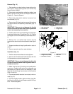
5. Support seat suspension to prevent it from falling.
Remove four (4) flange head screws (Figure 16 item 8)
and flange nuts (Figure 16 item 5) that secure seat sus-
pension to seat frame.
6. Removeseat suspension from machine. Locateand
retrieve four (4) spacers (Figure 16 item 7) from be-
tween seat suspension and seat frame.
7. Remove seat suspension components as needed
using Figures 15 and 16 as guides.
Installation (Figs. 15 and 16)
1. Install all removed seatsuspension components us-
ing Figures 15 and 16 as guides.
IMPORTANT: Take care to not damage the throttle
cable orelectricalharness wheninstalling seatsus-
pension to machine.
2. Positionseatbasecover andfour(4)spacers (Figure
16 item 7) to seat frame.
3. Position seat suspension to seat frame and secure
with four (4) flange head screws (Figure 16 item 8) and
flange nuts (Figure 16 item 5).
4. Install seat to machine (see Operator Seat Installa-
tion in thissection). Make sure to connectharness elec-
trical connector to the seat switch.
5. Connect negative battery cable to battery (see Bat-
tery Serviceinthe Serviceand Repairssection ofChap-
ter 5 -- Electrical System).
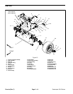
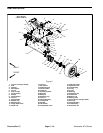
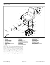
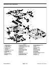
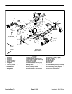
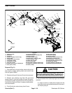
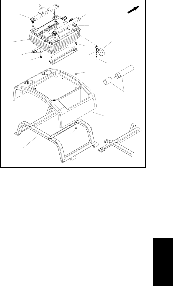
1. Seat suspension
2. Seat bracket (2 used)
3. Screw (4 used)
4. Seat frame
5. Flange nut (8 used)
6. Seatbase cover
7. Spacer (4 used)
8. Flange screw (4 used)
9. Cap (4 used)
10. Manual tube
11. R--clamp (2 used)
12. Flat washer (4 used)
13. Seat adjuster
14. Seat adjuster w/latch
Figure 16
1
2
4
3
5
6
7
8
FRONT
5
9
10
11
12
13
14
Chassis