


Reelmaster 5010 Series Page 5 -- 41 Electrical System
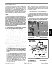
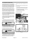
Temperature Sender
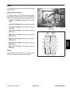
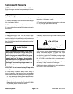
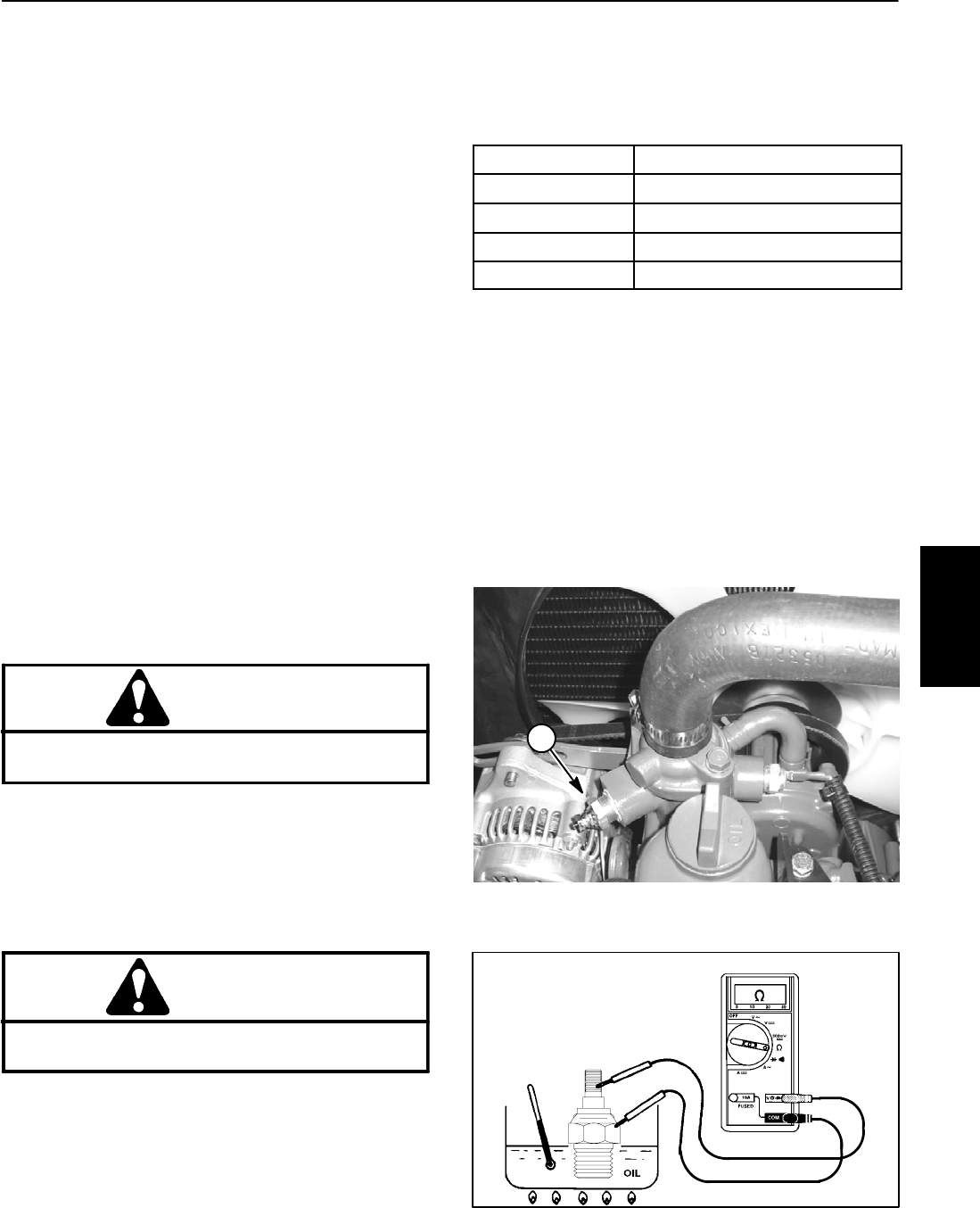
The temperature sender is attached to the water pump
housing on the engine and has a gray wire attached to
it(Fig. 53).Theresistance ofthe temperaturesenderre-
duces as the engine coolant temperature increases.
The changingresistance of thetemperature sender sig-
nals the console temperature gauge to indicate engine
coolant temperature level during machine operation.
When coolant temperature rises to approximately
221
o
F (105
o
C), temperature sender resistance causes
the temperature gauge to provide an input to the Elec-
tronic C ontrol Module (ECM). This ECM input causes
the high temperature warning light to illuminate and the
cuttingreelsto shutdown.The temperaturegauge,tem-
perature sender and circuit wiring should be tested as
an ECM input with the Diagnostic Display (see Special
Tools and Troubleshooting in this chapter).
Iftheexcessive coolanttemperaturecaused theECMto
shut down the cutting reels, the Diagnostic light can be
used to identify the fault (see Diagnostic Light in the
Troubleshooting section of this chapter).
Testing
1. Park machine on a level surface, lower cutting units,
stop engine, apply parking brake and remove key from
ignition switch. Open hood to gain access to engine.
CAUTION
Make sure engine is cool before removing the
temperature sender from engine.
2. Lower the coolant level in the engine, remove wire
harness connector from temperature sender and re-
move the sender from the engine.
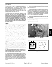
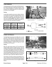
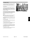
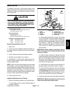
3. Put the end of the sender in a container of oil with a
thermometer and slowly heat the oil (Fig. 54).
CAUTION
Handle the hot oil with extreme care to prevent
personal injury or fire.
NOTE: Prior to taking resistance readings with a digital
multimeter,s hort the meter test leadstogether. The me-
ter will display a small resistance value (usually 0.5
ohms or less). This resistance is due to the internal re-
sistance of the meter and test leads. Subtract this value
fromfrom themeasuredvalueof thecomponent youare
testing.
4. Check resistance of the sender with a multimeter
(ohms setting) as the temperature increases. Replace
sender if specifications are not met.
COOLANT TEMP
TEMP SENDER RESISTANCE
100
o
F(38
o
C) 460 ohms (approximate)
160
o
F(71
o
C) 140 ohms (approximate)
200
o
F(93
o
C) 54 to 78 ohms
221
o
F (105
o
C) 50 ohms (approximate)
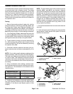
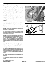
5. After testing, install sender to the engine housing.
A. Clean threads ofhousing and sender thoroughly.
Apply thread sealant to the threads of the sender.
B. Thread sender into the housing. Torque sender
from 16 to 20 ft--lb (22 to 27 N--m).
C. Reconnect harness wire connector to sender.
6. Fill engine cooling system.
7. Lower and secure hood.
1. Temperature sender
Figure 53
1
Figure 54
Electrical
System