


Reelmaster 5010 Series Hydraulic System (Rev. C)Page 4 -- 53
IMPORTANT: When capping lift cylinder fitting and
hydraulic hose end, use a steel cap and plug to en-
sure that fluid leakage will not occur. Plastic plugs
will not hold hydraulic pressure that will be devel-
oped during this test procedure.
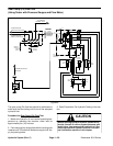
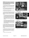
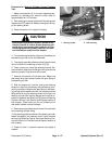
4. Place a steel cap on the open lift cylinder fitting to
seal the lift cylinder. Also, install a steel plug in the open
endofthe disconnectedhosetopreventleakage orcon-
tamination.
5. Slowly lower the jack and remove it from under the
lift arm. The cutting unit should settle slightly and then
be supported by the capped lift cylinder.
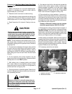
6. Marktheposition oftheliftcylinderrod attheliftcylin-
der head with a piece of tape (Fig. 50).
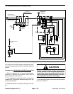
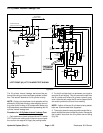
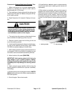
7. Leave the machine parked for two ( 2) hours and
monitor the lift cylinder. The weight of the cutting unit
may cause the lift cylinder to gradually extend. Use the
tape location to determine lift cylinder rod movement
(Fig. 51).
A. If lift cylinder rod movement is less than 1.250”
(31.7mm)aftertwo (2)hours,makesurethatthecut-
ting unit has not settled to the ground. If the cutting
unitisstillsuspended aftertwo(2)hoursandliftcylin-
der rod movement is less than 1.250” (31.7 mm),
consider that the lift cylinder is in good condition. A
cylinder in good, usable condition will show minimal
movement.
B. Rod movementin excess of 1.250” (31.7 mm)af-
ter two (2) hours indicates that the lift cylinder may
have internal seal damage or excessive wear. Re-
move and inspect the lift cylinder (see Lift Cylinder
and Lift Cylinder Service in the Service and Repairs
section of this chapter).
8. Once lift cylinder condition has been determined,
use a jack to raise the lift arm slightly which will remove
the load from the lift cylinder. Leave the jack to support
the lift arm and to prevent it from lowering. Remove the
cap from the cylinder fitting and the plug from the hy-
draulic hose.Connect the hydraulichose to the liftcylin-
der fitting.
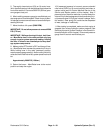
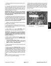
9. Remove jack from under the lift arm. Start engine
and operate lift cylinders through several up and down
cycles. Stop the engine and check for any leakage.
10.If needed, repeat steps 2 through 10 for other lift cyl-
inders.
11.Check oil level in hydraulic reservoir.
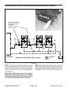
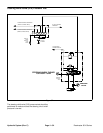
1. Lift cylinder (#5 shown)
2. Cylinder rod end fitting
3. Hydraulic hose
Figure 49
3
2
1
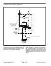
1. Lift cylinder rod
2. Lift cylinder head
3. Tape (initial position)
Figure 50
2
1
3
1. Tape (after 2 hours) 2. Cylinder rod movement
Figure 51
2
1
Hydraulic
System