


Reelmaster 5010 Series Page 5 -- 1 Electrical System
Chapter 5
Electrical System
Table of Contents
GENERAL INFORMATION 1.....................
ELECTRICAL DIAGRAMS 1......................
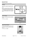
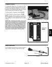
SPECIAL TOOLS 2.............................
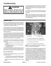
TROUBLESHOOTING 4.........................
Diagnostic Light 4.............................
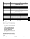
Retrieving Fault Codes 4....................
Clearing Fault Codes 5......................
Diagnostic Display 6..........................
Verify Diagnostic Display Input Functions 6.....
Verify Diagnostic Display Output Functions 8...
Electronic Control Module Logic Chart 9.........
Starting Problems 10..........................
General Run and Transport Problems 12.........
Cutting Unit Operating Problems 13.............
TurfDefender
TM
Leak Detector (Optional) 15......
ELECTRICAL SYSTEM QUICK CHECKS 18.......
Battery Test (Open Circuit Test) 18..............
Charging System Test 18......................
Glow Plug System Test 18.....................
Check Operation of Interlock Switches 19........
ADJUSTMENTS 20.............................
Traction Neutral Switch 20.....................
Parking Brake Switch 21.......................
Up Limit Switch 22............................
COMPONENT TESTING 23......................
Ignition Switch 23.............................
Indicator Lights 24............................
Hour Meter 25................................
Temperature Gauge 25........................
PTO Switch 26...............................
Traction Neutral Switch 27.....................
Seat Switch 28...............................
Headlight Switch 29...........................
Parking Brake Switch 30.......................
Up Limit Switch 31............................
Joystick Raise and Lower Switches 32...........
Mow/Transport Switch 33......................
Backlap Switches 34..........................
Start Relay 35................................
Main Power and Glow Relays 36................
Electronic Control Module (ECM) 37.............
Diode Assembly 38...........................
Fusible Link Harness 38.......................
Fuses 39....................................
Hydraulic Solenoid Valve Coil 40................
Temperature Sender 41........................
High Temperature Shutdown Switch 42..........
Oil Pressure Switch 43.........................
Fuel Stop Solenoid 44.........................
Fuel Pump 45................................
SERVICE AND REPAIRS 46.....................
Battery Storage 46............................
Battery Care 46...............................
Battery Service 47............................
Control Arm 50...............................
Hydraulic Solenoid Valve Coil 52................
Backlap Switches 53..........................
TurfDefender
TM
Leak Detector (Optional) 54......
General Information
The Traction Unit Operator’s Manual provides informa-
tion regarding the operation, general maintenance and
maintenance intervals for your Reelmaster machine.
Refer to that publication for additional information when
servicing the machine.
Electrical Diagrams
The electrical schematic, electrical circuit drawings and
wire harness drawings for Reelmaster 5010 series ma-
chines are located in Chapter 9 -- Foldout Drawings.
Electrical
System