


Reelmaster 5010 Series Page 5 -- 9 Electrical System
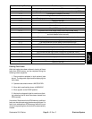
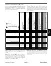
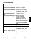
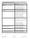
Electronic Control Module Logic Chart
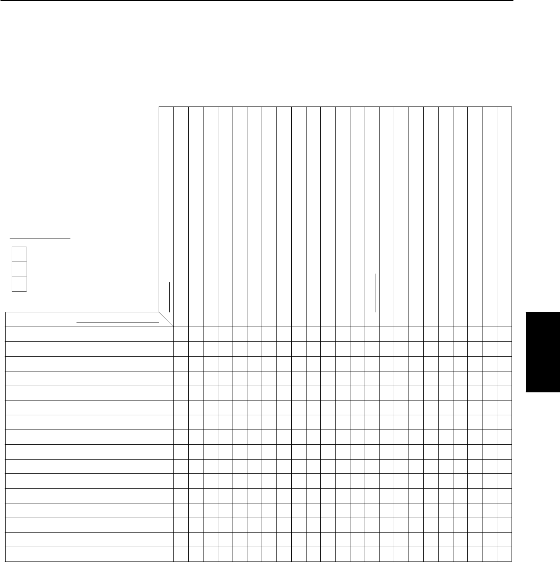
Each line of the following chart identifies the necessary
componentposition (INPUTS)inorderfor theElectronic
Control Module (ECM) to energize the appropriate
OUTPUTS for machine operation.
Example: To start the engine with no operator in the
seat, when the ignition key is in start, the traction pedal
is in neutral and the parking brake is applied, the glow
plugs and other necessary engine starting components
will be energized.
X
INPUTS
MACHINE FUNCTION
Preheat
Start (No Operator in Seat)
Start (Operator in Seat)
Run (No Operator in Seat)
Run (Operator in Seat)
Lower Cutting Units to Ground
Mow (C.U. on Ground)
Raise (from Mow to Turn Around Position)
Lower/Mow (from TurnAround Position)
Raise (to Transport Position)
Stop Backlap (Front C.U.)
Stop Backlap (Rear C.U.)
Diagnostic Light ECM Fault Retrieval
Clearing ECM Faults (From Retrieval Mode)
Inititate Backlap (Front C.U.)
Initiate Backlap (Rear C.U.)
Ignition Key in RUN
Ignition Key in START
Traction Pedal in Neutral
Seat Occupied
Parking Brake Applied
Normal Coolant Temperature
Joystick Pulled to Rear (Raise)
Joystick Pushed Forward (Lower/Raise)
PTOSwitchinON
Mow/Transport Lever in Mow
Up Limit Switch Closed (C.U. Lowered)
Front C.U. in Backlap Position
Rear C.U. in Backlap Position
OUTPUTS
SV1 (Front Lift Cylinders) Energized
SV2 Energized
SV3 (Rear Lift Cylinders) Energized
SVRV Energized
MSV1 (Rear Reel Motors) Energized
MSV2 (Front Reel Motors) Energized
Engine Run Solenoid Hold Coil Energized
Engine Start (Run Solenoid and Start Solenoid Energized)
X
X
X
X
X
X
X
X
X
X
X
X
X
X
X
X
X
X
X
X
X
X
X
X
X
XX
X
XX
X X XXX
X X XXX
XX XXX
X
XXXXXX
X X XXXX
XXXXXX
XX XXX X
X
XXX
P
Engine Glow Plugs Energized
P
PP
P
P
P
PPP
PP
PPPP
PPPPP
PPPP
P
P
P
P
P
P
P
P
P
P
P
X
P
Component (Input) Position
Not Relevent for Function
Component (Output) Energized
KEY TO CHART
X
NOTE: ForStartmachinefunction,thejoystickmustbe
in the neutral (center) position andthe PTO switch must
be OFF.
NOTE: When the Lower/Mow machine function is
completed, thefront cuttingunits engagewhile lowering
to the ground followed shortly by the rear cutting units
engagingwhile loweringtotheground.Thetiming ofthis
sequence is provided by the ECM.
NOTE: The Diagnostic Light ECM Fault Retrieval
machine function requires that the seat be unoccupied,
the mow/transport lever be in the transport position, the
PTO switch be OFF and both front and rear C.U. in the
mow position.
Electrical
System