


Reelmaster 5010 Series Hydraulic System (Rev. C)Page 4 -- 87
11.If solenoid coil was removed:
A. Carefully install coil onto the cartridge valve.
B. Install nut andtorque nut to 48 to 60 in--lb (5.4 to
6.7 N--m).
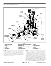
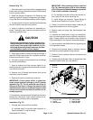
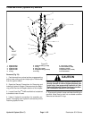
12.If flow control cartridge valve was removed, install
rotary handle to v alve stem (Fig. 72):
A. Placehandlebase onflowcontrol valveandposi-
tion alignment mark on base with number 1 on man-
ifold. Secure base with two (2) set screws. Apply a
light coating of grease to chamfer on top of base to
ease seal installation.
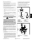
B. Make sure that sleeve bearing is in handle cap. If
necessary, press sleeve bearing into cap. Install lip
seal on cap with seal lip facing down.
C. Place bushing onto cartridge valve stem. Use a
small amount of grease to keep bushing toward the
topofthevalvestem.
D. Place compression spring and detent pin into
handle cap. Use a small amount of grease to hold
detent pin in place.
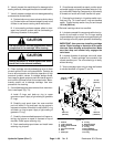
E. Make sure that flow control cartridge is closed by
rotating valve stem fully clockwise. During handle
installation, DO NOT rotate valve stem or speed ad-
justment will be incorrect.
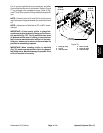
F. Press handle cap onto valve stem with arrow on
cappointingtonumber 9onmanifold.Makesurethat
detent pin and spring stay positioned in cap.
G. While pressing on the cap to keep the lip seal in
place, rotate cap in a clockwise direction until the ar-
row onthe cap aligns withnumber 1 on the manifold.
By rotating the cap clockwise, the valve will remain
closed. Install screw to retain cap.
H. Makesure thatalignmentmarks oncap andbase
areinlineand thatarrowoncapispointingtonumber
1 on manifold. Tighten two (2) set screws to secure
handle cap.
Hydraulic
System