


Rev. B
Reelmaster 5010 Series Page 5 -- 31 Electrical System
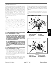
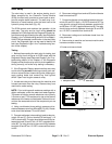
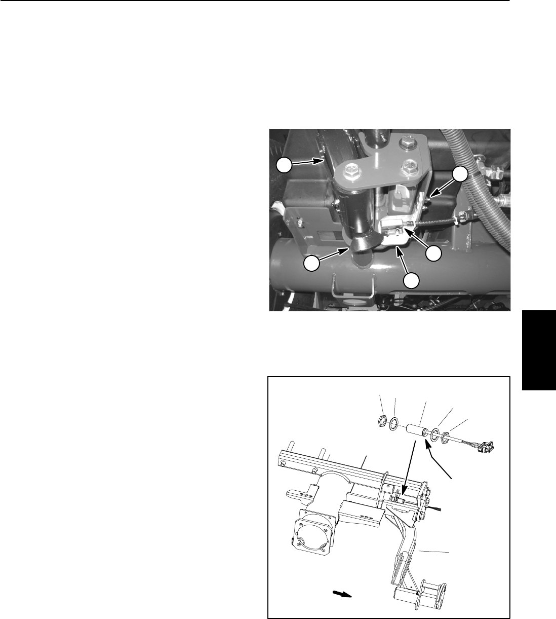
Up Limit Switch
The up limit switch is a normally open proximity switch
that closes when the cutting units are in the lowered
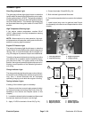
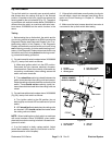
position. A bracket on the front, right lift arm acts as the
sensing platefor the uplimit switch (Fig.37). The switch
on machines with a serial number below 310000000 is
different than the switch on machines with serial num-
bers above 310000000 but the switch function is the
same.
Testing
1. Before testing the up limit switch, the switch and its
circuit wiring should be tested as an ECM input with the
Diagnostic Display (see Diagnostic Display in the Trou-
bleshooting section of this chapter). If the Diagnostic
Display verifies that the up limit switch and circuit wiring
arefunctioningcorrectly,nofurtherswitchtesting isnec-
essary. If the Diagnostic Display determines that the up
limitswitchandcircuitwiringarenotfunctioningcorrect-
ly, proceed with testing procedure.
2. On machines with serial numbers below310000000
(Fig. 37), test up limit switch as follows:
A. Make sure ignition switch is in the OFF position.
Disconnect the wire harness electrical connector
fromthe switch.Check thecontinuity oftheswitch by
connecting a multimeter (ohms setting) across the
switch connector terminals.
B. Thereshould becontinuity (closed)between the
switch terminals when the cutting units are lowered.
Raisethecuttingunitsandcheck thecontinuityofthe
switch. There should not be continuity (open) be-
tweenthe switchterminalswhen thecuttingunits are
raised.
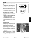
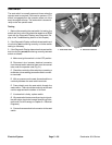
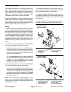
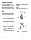
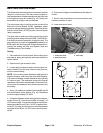
3. Onmachines with serialnumbers above310000000
(Fig. 38), test up limit switch as follows:
A. Turn ignition switch to the ON position (do not
start engine) and check LED on cable end of up limit
switch.
B. LEDshouldbeilluminatedwhenthe cuttingunits
are lowered. LED should not be illuminated when
the cutting units are raised.
NOTE: When installingthe up limit switch on machines
with serial numbers below 310000000, place switch
plate tab into switch mounting hole that is closest to tar-
get end of switch.
4. If up limit switch is faulty, replace switch. Adjust
switch after installation (see Up Limit Switch in the Ad-
justments section of this chapter).
5. Ifthe up limitswitch testscorrectly and acircuit prob-
lem still exists, check wire harness (see Wiring Sche-
matic and Circuit Drawings in Chapter 9 -- Electrical
Diagrams).
6. Make sure that wire harness electrical connector is
connected to the up limit switch after testing.
1. Lift arm
2. Up limit switch
3. Sensing plate
4. Lock nut (2 used)
5. Switch bracket
Figure 37
1
2
3
4
5
1. Up limit switch
2. Lock washer
3. Jam nut
4. Lift arm
Figure 38
SERIAL NUMBER
ABOVE 310000000
2
3
1
LED location
2
3
4
FRONT
Electrical
System