


Reelmaster 5010 Series Hydraulic System (Rev. C)Page 4 -- 37
CAUTION
Before openinghydraulic system, operateall hy-
draulic controls to relieve system pressure and
avoid injury from pressurized hydraulic oil. See
Relieving HydraulicSystemPressure inthe Gen-
eral Information section of this chapter.
5. Attachaheavychaintotherearofthemachineframe
and an immovable object to prevent the machine from
moving during testing.
6. Chock front wheels to prevent wheel rotation. Make
sure parking brake is applied.
NOTE: Ifmachineisequipped withoptionalCrossTrax-
TM
AWD, jack up and support the rear wheels off the
ground to allow flow through the rear wheel motors.
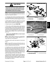
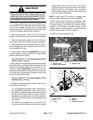
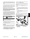
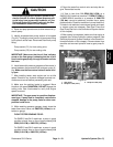
7. Thoroughly clean junction of hydraulic hose and
right side elbow fitting on bottom of traction pump (Fig.
34). Disconnect hose from traction pump fitting.
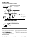
IMPORTANT: Make sure that the oil flow indicator
arrow on the flow meter is showing that the oil will
flow from the pump, through the tester and into the
hydraulic hose.
8. Install tester with pressure gauges and flow meter in
series with the traction pump and the disconnected
hose. Make sure the tester flow control valve is fully
open.
9. Start engine and move throttle to full speed (3200
RPM).
CAUTION
Use extreme caution when performing test. The
front tires on the ground will be trying to move
themachineforward.
10.Slowly push traction pedal in forward direction until
1000 PSI is displayed on the tester pressure gauge.
11.Total front wheel motor internal leakage will be
shown on flow meter in GPM (LPM).
12.Release traction pedal, shut engine off, rotate both
front wheels and retest. Testing of wheel motor leakage
in three (3) different wheel positions will provide the
most accurate test results. Record measured front
wheelmotor internalleakage forallthree (3)wheelposi-
tions.
13.If total leakage for the front wheel motors is more
than 1.5GPM (5.7 LPM),one or both ofthe motors may
be faulty. Individual front wheel motor testing is neces-
sary.
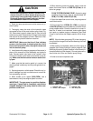
14.To test individual front wheel motors:
A. Remove front wheel from wheel motor that is not
being tested. Remove wheel shield to allow access
to hydraulic tubes and fittings on wheel motor. Re-
move fasteners that secure front hydraulic tube r--
clamps to frame.
B. On the front wheel motor that is not being tested,
thoroughlycleanjunction ofbothhydraulictubesand
wheel motor fittings. Disconnect both hydraulic lines
from wheel motor that is not being tested. Cap dis-
connected hydraulic lines and wheel motor fittings.
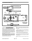
C. Use the procedure described in steps 8 to 10
above to identify individual front wheel motor leak-
age. Individual motor internal leakage will be shown
on flow meter in GPM (LPM). Flow should be less
than 1.5 GPM (5.7 LPM) for the tested wheel motor.
D. If other front wheel motor requires testing, com-
plete steps A, B and C for remaining wheel motor.
15.After testing is completed, stop engine and then re-
lievehydraulic systempressure(See RelievingHydrau-
lic System Pressure in the General Information section
of this chapter). Disconnect tester from hydraulic fitting
and hose. Connect hoseto pump elbow fitting. Remove
caps fromhydraulic tubesand reconnecttubes towheel
motor.Securehydraulictubestomachine withr--clamps
and removed fasteners. Install wheel shield and
wheel(s) (see Wheels in the Service and Repairs sec-
tion of Chapter 6 -- Chassis).
1. Traction pump
2. RH elbow fitting
3. Hyd hose (forward)
4. LH elbow fitting
5. Hyd hose (reverse)
Figure 34
2
3
1
FRONT
RIGHT
4
5
2WD MACHINE SHOWN
Hydraulic
System