


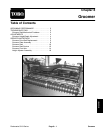
Reelmaster 5010 Series
Cutting Units (Rev. C)
Page 7 -- 37
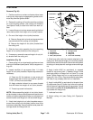
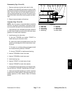
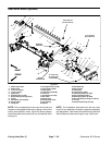
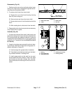
Disassembly (Fig. 40)
1. Positionmachine on aclean andlevel surface,lower
cutting units,stop engine,engage parkingbrake andre-
move key from the ignition switch.
2. To remove roller brush from brush shaft:
A. Remove the non--drive brush bearing housing
(item 30) from cutting unit.
B. Slide excluder seal from roller brush shaft.
C. Removelocknut andJ--boltfrom bothendsofthe
brush.
D. While rotating brush, slide brush from the shaft.
3. Disassemble rollerbrush components as necessary
using Figures 40 as a guide.
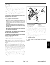
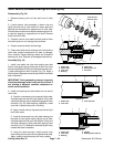
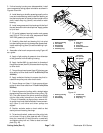
Assembly (Fig. 40)
1. If brush was removed from shaft, slide brush onto
shaftwhilerotatingbrush.Securebrushtoshaftwithtwo
(2) J--bolts and locknuts. Make surethat the J--bolts are
installed with the threaded portion on the outside of the
brush(Fig.41). Torquelocknutsfrom20 to25in--lb(2.3
to 2.8 N--m).
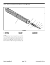
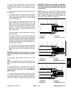
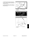
2. If seals or bearings were removed from brush bear-
ing housings, install new components noting proper ori-
entation as shown in Figure 42.
A. Pack bearings with grease before installation.
B. Press bearing into bearing housing so that bear-
ing contacts shoulder in housing bore.
C. Install grease seals so that seal lips are posi-
tioned toward the brush location. Press inner seals
into housing so that seal contacts bore shoulder.
Press outerseals into housinguntil innerseal is con-
tacted.
1. Roller brush shaft
2. J--bolt
3. Roller brush
4. Lock nut
Figure 41
1
2
3
4
20 to 25 in--lb
(2.3 to 2.8 N--m)
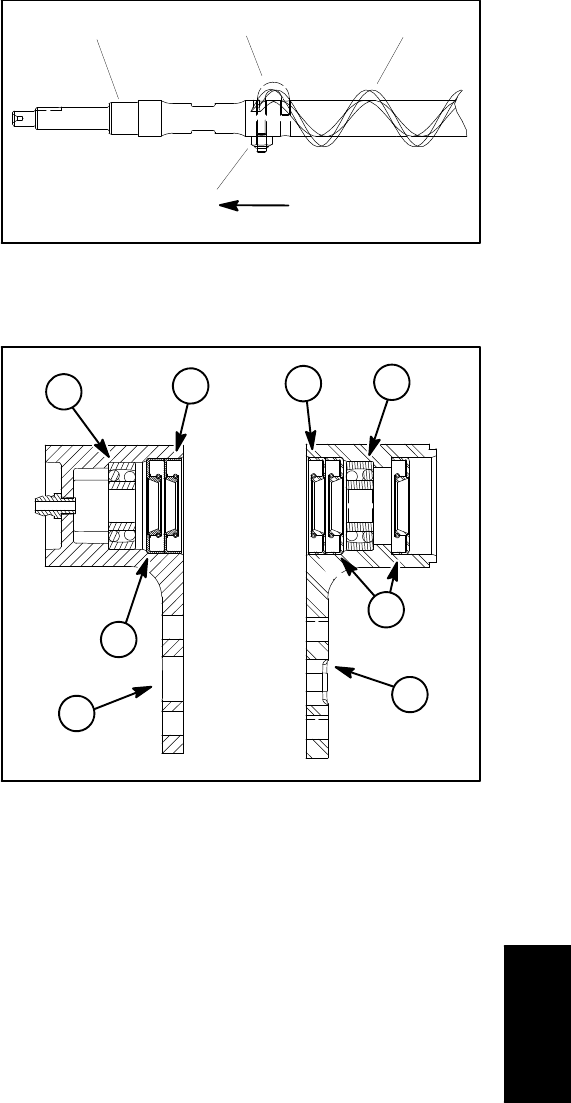
1. Bearing
2. Inner grease seal
3. Outer grease seal
4. Housing (non--driven)
5. Housing (driven)
Figure 42
2
2
1
1
4
5
3
3
Cutting
Units