


Reelmaster 5010 Series Hydraulic System (Rev. C)Page 4 -- 69
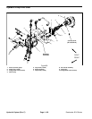
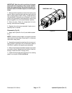
Removal (Fig. 60)
1. Parkthe machineona levelsurface, engageparking
brake, lower cutting units and stopengine. Remove key
from the ignition switch.
2. Read the General Precautions for Removing and
Installing Hydraulic System Components at the begin-
ning of the Service and Repairs section of this chapter.
CAUTION
Before openinghydraulic system, operateall hy-
draulic controls to relieve system pressure and
avoid injury from pressurized hydraulic oil. See
Relieving HydraulicSystemPressure inthe Gen-
eral Information section of this chapter.
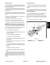
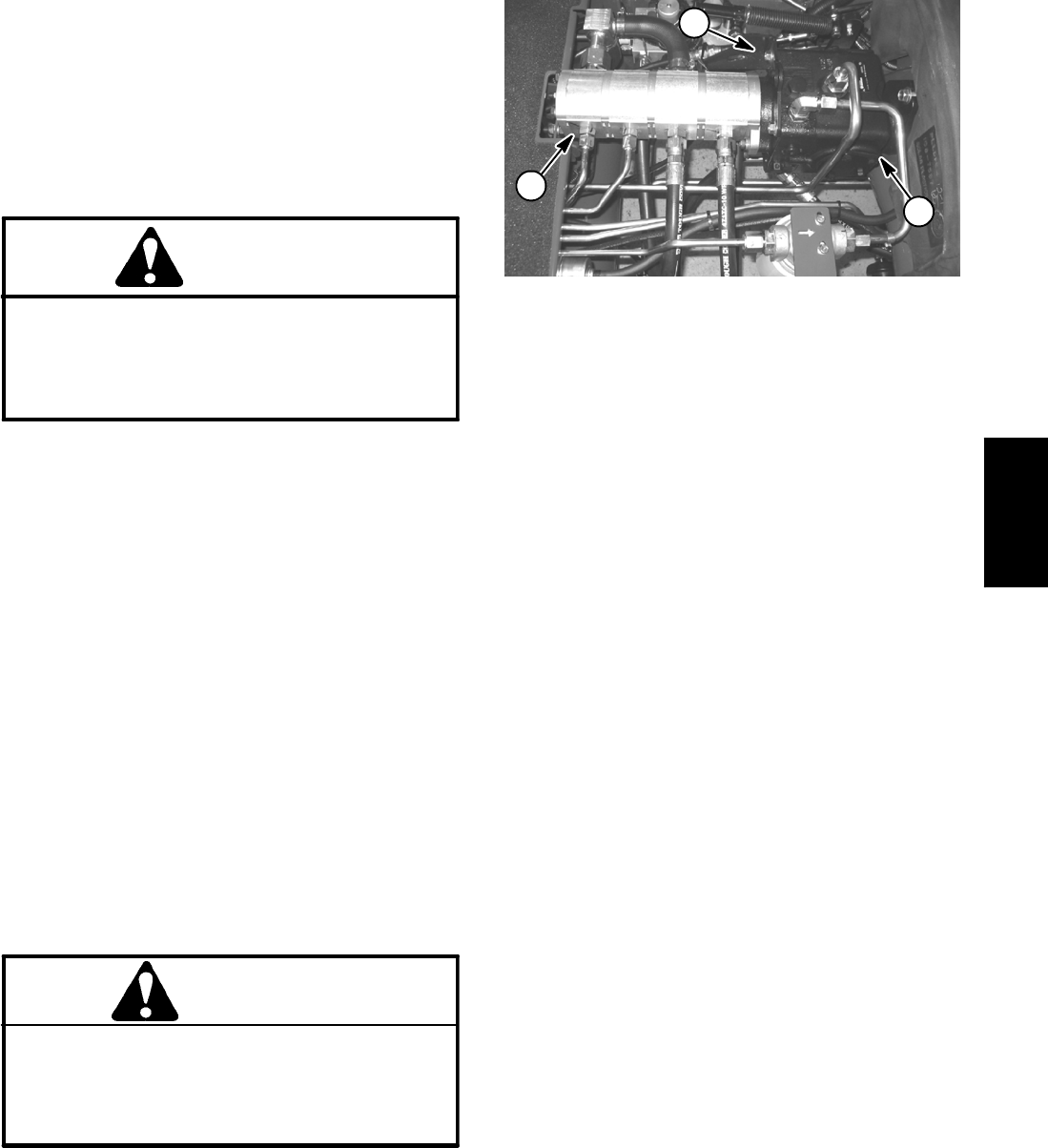
3. To prevent contamination of the hydraulic system,
thoroughly clean traction and gear pump assembly and
all hydraulic connections.
4. Label hydraulic hoses toassist in assembly. Discon-
nect all hydraulic hoses and tubes from fittings on the
traction and gear pump assembly. Allow hydraulic lines
to drain into a suitable container. Plug or cap openings
of pumps and lines to prevent contamination.
5. Remove hydraulic pump drive shaft (see Hydraulic
Pump Drive Shaft Removal in this section).
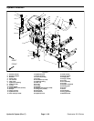
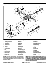
6. Remove cap screw and lock nut that secure plate
(item 10) to pump lever. Remove two (2) flange head
screws (item 3) that secure cable bracket to traction
pump. Carefully position traction control cable and
bracket away from traction pump.
7. Disconnect harness electrical connector from trac-
tion neutral switch and position harness away from
transmission.
CAUTION
Make sure lift or hoist can support the total
weight of the pump assembly before removing
the cap screws from the engine and engine
brackets.Pump assemblyweighsapproximately
67 pounds (30.5 kg).
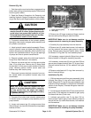
8. Connecta liftor hoistto holein tractioncable bracket
on traction pump to s upport pump assembly and for
pump removal.
9. Loosen and remove two (2) carriage screws (item
38) and flange nuts (item 36) that secure pump support
bracket to frame.
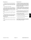
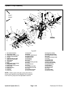
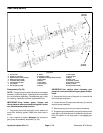
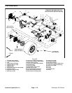
1. Piston (traction) pump
2. Gear pump
3. Traction cable bracket
Figure 61
2
1
3
10.Remove two (2) flange screws and flange nuts that
secure traction pump flange to machine frame.
IMPORTANT: Make sure to not damage machine
components while removing the pump assembly.
11.Carefully lift pump assembly from the machine.
12.Remove two (2) socket head screws, lock washers
and flat washers that secure gear pump to traction
pump. Remove gear pump from traction pump. Locate
and discard O--ring (item 30) from between pumps.
13.If necessary, remove hydraulic fittings from pumps.
Note orientation of fittings for assembly purposes.
14.If necessary, remove two (2) lock nuts (item 35) that
secure pump support bracket (item 37) to gear pump.
Remove bracket and two (2) flat washers from gear
pump.
15.Remove and discard all O--rings from removed hy-
draulic lines and fittings.
Installation (Fig. 60)
1. If fittings were removed from pump assembly, lightly
lubricate new fitting O--rings with clean hydraulic oil.
Install fittings with O--rings to the pump assembly (see
Hydraulic Fitting Installation in the General Information
section of this chapter). Orientate fittings as noted dur-
ing removal.
2. Ifpump support bracket(item 37) wasremoved from
gear pump, fit flat washers and bracket to gear pump
and secure with two (2) lock nuts.
3. Lubricate and position new O--ring (item 30) be-
tween pumps. Position gear pump to traction pump and
secure with two (2) socket head screws, lock washers
and flat washers.
IMPORTANT: Make sure to not damage machine
components while installing the pump assembly.
Hydraulic
System