


Rev. B
Reelmaster 5010 SeriesHydraulic System (Rev. C) Page 4 -- 86
6. Visually inspect the manifold port for damage to the
sealing surfaces, damaged threads and contamination.
7. Visually inspect cartridge valvefor damaged sealing
surfaces and contamination.
A. Contaminationmay cause valvesto stickor hang
up.Contaminationcanbecomelodgedinsmallvalve
orifices or seal areas causing valve malfunction.
B. If valve sealing surfaces appear pitted or dam-
aged, the hydraulic system may be overheating or
there may be water in the system.
CAUTION
Use eye protection such as goggles when using
compressed air for cartridge valve cleaning.
CAUTION
Abrupt movement of internal spools can cause
stored fluid to be released suddenly.
8. Clean cartridge valve by s ubmerging valve in clean
mineral spirits to flush out contamination. Particles as
fine as talcum powder can affect the operation of high
pressure hydraulic valves. If cartridge design allows,
use a wood or plastic probe to push the internal spool in
and out20 to30 times to flush outcontamination. Be ex-
tremely careful not to damage cartridge. Use com-
pressed air for cleaning.
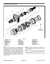
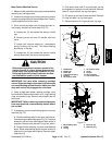
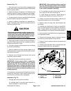
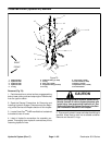
9. If mow/backlap spool was removed from mow man-
ifold, install spool (Fig. 73):
A. Install O--rings and back--up ring to upper
grooves on spool. Apply a light coating of grease to
O--r ings.
B. Carefully push spool down into mow manifold
port until lower O--ring and back--up ring groove is
exposed on bottom of manifold. Install lower O--ring
and back--up ring to spool. Apply a light coating of
grease to O--ring.
C. Carefullyraise mow/backlap spooluntil upperre-
taining ring groove on spool is exposed on top of
manifold. Install upper retaining ring.
D. Push mow/backlap spool down and install lower
retaining ring to spool.
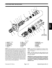
E. If handlewas removed from spool,position spool
so handle location of spoolis between stop pins.Ap-
ply Loctite 603 Retaining Compound (or equivalent)
to threads on handle and install handle into spool.
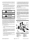
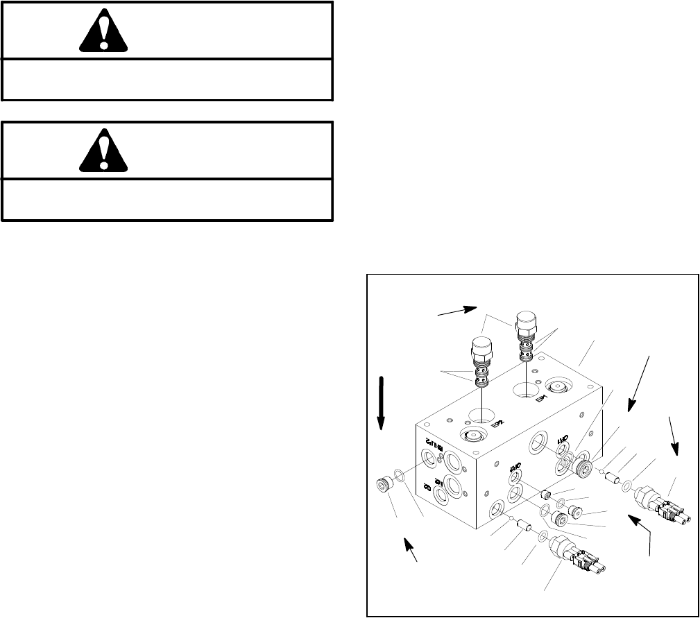
F. Place ball and dowel pin in backlap switch man-
ifold port (Fig. 74). Install new O--ring onto backlap
switch. Thread backlap switch into port and torque
15 ft--lb (20 N--m).
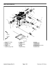
10.Reinstall cartridge valve into manifold:
A. Lubricatenew seal kitcomponents withclean hy-
draulic oil and install on valve. The O--r ings, sealing
ringsandbackuprings mustbearrangedproperlyon
the cartridge valve for proper operation and sealing.
IMPORTANT: Use care when installing cartridge
valves. Slight bending or distortion of the stem
tube can cause binding and malfunction. Make
sure that deep well socket fully engages the
valve base.
B. Lubricate threads of cartridge valve with clean
hydraulic oil. Thread cartridge valve carefully into
correct manifold port. The valve should go in easily
without binding.
C. Torque cartridge valve using a deep well socket
to values identified in Figures 71 and 74.
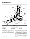
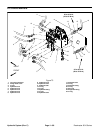
1. Seal kit
2. Logic cartridge
3. Mow control manifold
4. O--ring
5. Plug (zero leak #8)
6. Ball
7. Dowel pin
8. O--ring
9. Backlap switch
10. Orifice (0.055)
11. O--ring
12. Plug (SAE #4)
13. Plug (zero leak #6)
14. O--ring
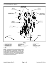
Figure 74
165 in--lb
(18.6 N--m)
198 in--lb
(22 N--m)
41 ft--lb
(55 N--m)
15 ft--lb
(20 N--m)
20 ft--lb
(27 N--m)
UP
4
3
1
2
9
10
11
8
5
6
7
12
1
6
7
9
8
13
14
13
14