


Rev. A
Reelmaster 5010 SeriesPage 5 -- 8Electrical System
Verify Diagnostic Display Output Functions
The Diagnostic Display also has the ability to detect
which output solenoids or relays are turned on by the
ECM. This isa quick way to determineif a machinemal-
function is electrical or hydraulic.
NOTE: Anopenoutput(e.g.anunpluggedconnectoror
a broken wire) cannot be detected with the Diagnostic
Display.
1. Park machine on a level surface, lower the cutting
units, stop the engine and engage the parking brake.
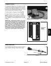
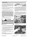
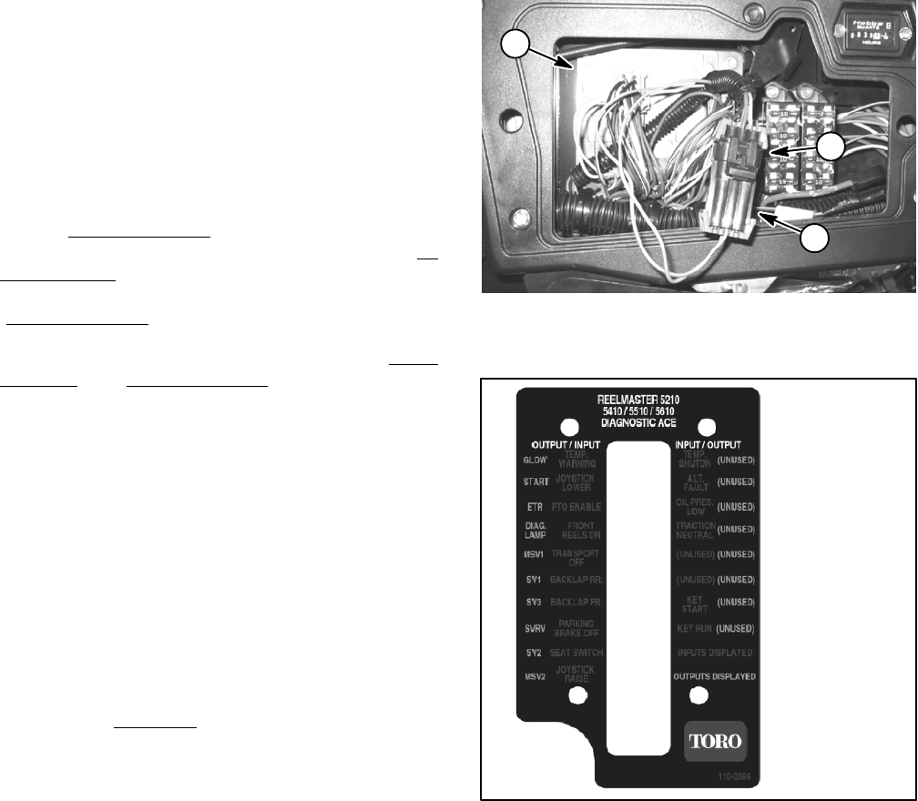
2. Open control panel cover. Locate wire harness and
connectors near ECM. Carefully unplug loop back con-
nector from harness connector (Fig. 10).
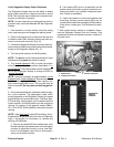
3. ConnecttheDiagnosticDisplayconnectortothehar-
nessconnector.Makesurecorrectoverlaydecalisposi-
tioned on the Diagnostic Display (Fig. 11).
4. Turn the ignition switch to the RUN position.
NOTE: The redtext on the overlay decal refers to input
switches and the green text refers to outputs.
5. The “outputs displayed
” LED, on lower right column
of the Diagnostic Display, should be illuminated. If “
in-
puts displayed
” LEDis illuminated, press the togglebut-
ton on the Diagnostic Display to change the LED to
“outputs displayed
”.
NOTE: It may be necessary to toggle between “
inputs
displayed
” and“outputs displayed” several timesto per-
form the following step. To change from inputs to out-
puts, press toggle button once. This may be done as
often as required. Do not press and hold toggle but-
ton.
6. Sit on seat and attempt to operate the desired func-
tion of the machine. The appropriate output LED’s
should illuminate on the Diagnostic Display to indicate
thatthe ECMis turningon thatfunction.The Glow,Start,
ETR and Diag. Lamp outputs can be checked with the
ignition switch in the RUN position and the engine not
running. For testing of the solenoid outputs ( MSV1,
SV1, SV3, SVRV, SV2 and MSV2), the engine must be
running.
NOTE: Ifthe “diag.lamp
” outputLED isblinking, this in-
dicates an ECM fault has occurred. Refer to Diagnostic
Light in this section for information on retrieval and
clearing of ECM faults.
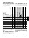
A. IfthecorrectoutputLED’sdonotilluminate, verify
that the required input switches are in the necessary
positions to allow that function to occur (see Elec-
tronic Control Module Logic Chart in this section).
Verify correct switch function.
B. If the output LED’s are on as specified, but the
machine does not function properly, suspect a non-
electrical problem (e.g. hydraulic component prob-
lem). Repair as necessary.
C. If each input switch is in the correct position and
functioning correctly, but the output LED’s are not
correctlyilluminated,thisindicates anECMproblem.
If this occurs, c ontact your Toro Distributor for assis-
tance.
7. After output function testing is completed, discon-
nect the Diagnostic Display from wire harness. Plug
loopback connectorinto harnessconnector.Installcon-
trol panel cover.
1. ECM location
2. Loopback connector
3. Harness connector
Figure 10
1
2
3
Figure 11
OVERLAY
DIAGNOSTIC
DISPLAY