


Rev. B
Reelmaster 5010 Series Hydraulic System (Rev. C)Page 4 -- 105
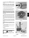
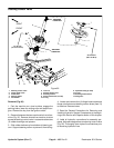
3. Using a spannerwrench, rotate head clockwise until
theedge oftheretaining ringappears inthebarrel open-
ing. Insert a screwdriver under the beveled edge of the
retainingringto startthe retainingring throughtheopen-
ing. Rotate the head counter--clockwise to remove re-
taining ring from barrel and head.
4. Remove plugs from ports. Extract shaft, head and
piston by carefully twisting and pulling on the shaft.
IMPORTANT: Do not clamp vise jaws against the
shaft surface. Clamp on the clevis ONLY.
5. Mountshaftsecurelyinaviseby clampingonthecle-
vis of the shaft. Remove lock nut and piston from the
shaft. Carefully slide head off the shaft.
6. Taking care to not scratch or damage the piston, re-
move cap seal and O--rings from the piston.
7. Taking care to not scratch or damage the head, re-
move O --ring, back--up washer, wiper and u--cup from
the head.
Inspection
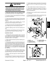
CAUTION
Use eyeprotectionsuch asgoggles whenusing
compressed air.
1. Wash all lift cylinder components in solvent. Dry
parts with compressed air.
2. Inspect internalsurface of barrel for deepscratches,
out--of--roundness and bending.
3. Inspect head, shaft and piston for excessive pitting,
scoring and wear.
4. Replacelift cylinderif internalcomponents arefound
to be worn or damaged.
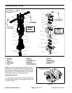
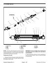
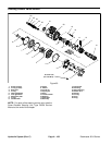
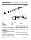
Assembly (Fig. 89)
1. Make sure all lift cylinder parts are c lean before as-
sembly.
2. Coat new O--rings, back--up washer and other seals
with clean hydraulic oil.
A. Carefully install cap seal and O--r ings to the pis-
ton.
B. Carefully install back--up washer, O--ring, u--cup
and wiper to the head.
IMPORTANT: Do not clamp vise jaws against the
shaft surface. Clamp on the clevis ONLY.
3. Mountshaftsecurelyinaviseby clampingonthecle-
vis of the shaft.
A. Coat shaft with clean hydraulic oil.
B. Slide head onto the shaft.
C. Install piston onto the shaft and secure with lock
nut. Torque lock nut from 30 to 35 ft--lb (41 to 47
N--m).
D. Remove shaft assembly from the vise.
IMPORTANT: Prevent damage when clamping the
hydraulic cylinder into a vise; clamp on the clevis
end of the barrel ONLY.
4. Mount barrel securely in a vise by clamping on the
clevis end of the barrel.
IMPORTANT: When installing the head into the bar-
rel, pay careful attention to the retaining ring slot in
thebarreltoinsuret hat thepistonandheadsealsdo
not lodge in the slot.
5. Coat all internal parts with a light coat of clean hy-
draulic oil. Slide piston, shaft and head assembly into
the barrel being careful not to damage the seals.
6. Secure head in barrel by installing retaining ring.
Align retaining ring hole in the head with the access slot
in the barrel. Insert the retaining ring hook into the hole
androtate headclockwise untiltheretaining ringis com-
pletely pulled into the barrel and the ring ends are cov-
ered.
Hydraulic
System