


Reelmaster 5010 Series
Cutting Units (Rev. C)
Page 7 -- 13
Leveling Rear Roller
The precision machined components of the cutting unit
frame keep the rear roller and cutting reel in alignment
(parallel). If the side plates are disassembled or as the
cutting reel wears, a limitedamount of side plate adjust-
ment is possible to make sure that the cutting unit is
properly aligned.
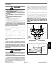
1. Place the assembled cutting unit on a surface plate.
2. Make sure that bedknife is properly adjusted to cut-
ting reel.
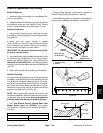
3. Using the surface plate, check if rear roller is level to
cutting reel by using a 0.005” (0.13 mm) shim at each
end of rear roller. If the shim will pass under the roller at
one endbut not theother, aframe adjustment should be
made.
NOTE: Cutting units with 5” diameter reel use two (2)
shoulder bolts to secure endplates to frame. Cutting
units with 7” diameter reel use three (3) shoulder bolts
to secure endplates to frame.
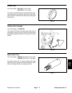
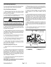
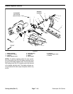
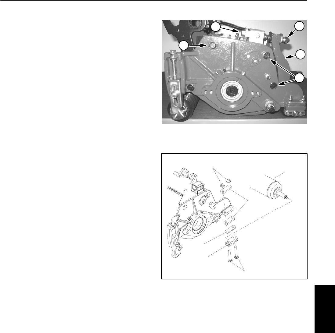
4. Loosen, but do not remove, shoulder bolts that se-
cure the side plate to the frame opposite the side that is
not level (Fig. 13).
5. Adjust the position of the side plate to parallel the
rear roller and cutting reel. Then, tighten the shoulder
bolts to a torque from 27 to 33 ft--lb (37 to 44 N--m).
6. Aftertighteningthes ide plate,rechecktherearroller.
If necessary, loosen and adjust second side plate.
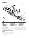
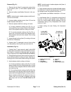
7. If rear roller is still not level after adjusting both side
plates, check to see if cutting reel is tapered (see Pre-
paring Reelfor Grindingin theService and Repairssec-
tionof thischapter). Ifcuttingreel isnottapered andrear
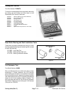
rolleris notlevel,a 0.010”shim (partnumber107--4001)
is available to allow additional rear roller adjustment.
The shim would be used on one side of the rear roller
and should be installed between the rear roller bracket
and roller shim (Fig. 14).
8. Afterleveling rearroller,completecutting unitset--up
and adjustment sequence.
1. Bedbar
2. Bedbar adjuster screw
3. Spring tension lock nut
4. Shoulder bolt
Figure 13
2
4
1
3
4
Cutting Unit with 7” Reel Shown
1. Rear roller assembly
2. Rear roller bracket
3. Carriage screw
4. Flange nut
5. Roller shim
6. 0.010” shim (if needed)
Figure 14
1
2
3
4
5
6
Cutting
Units