


Reelmaster 5010 Series
Cutting Units (Rev. C)
Page 7 -- 24
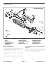
IMPORTANT: During cutting reel installation, keep in-
nerand outerbearingracesaligned. Ifbearingracesare
not aligned, binding will occur and reel installation may
cause bearing damage.
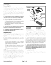
3. Carefully slide the cutting reel with bearings and
grease seals into the RH side plate. Make sure that
bearing is fully seated into side plate.
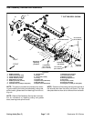
4. On LH side plate, loosen set screw (item 21) and
back--off (loosen) bearing adjuster nut (item 20) one
complete turn.
5. Slide the LH side plate onto the cutting reel assem-
bly, front roller and rear roller. Make sure that reel end
in RH side plate does not shift in position.
6. Install shoulder bolts (item 8) and flange nuts (item
24) that secure the LH side plate to the cutting unit
frame.Torque theshoulderbolts from27to33 ft-lbs(37
to 44 N --m).
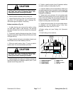
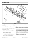
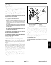
7. Apply Loctite #242 (or equivalent) to threads of
flange head screw that secures support tube, frame
spacer and carrier frame to LH side plate (Fig. 27).
Install screw and torque from 27 to 33 ft-lbs (37 to 44
N--m). After tightening screw, check the clearance be-
tween the carrier frame and side plate. If clearance is
more than 0.090” (2.3 mm), remove flange head screw
and position shim(s) (part number 67--9410) between
carrier frame and side plate so that clearance is less
than 0.090” (2.3 mm). Make sure that the carrier frame
pivots freely after assembly.
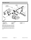
8. Install cap screw and flat washer that secure rear
grass shield to LH side plate (Fig. 27). Torque screw
from 15 to 19 ft -lbs (20 to 25 N--m).
9. Secure the bedbar assembly to LH side plate (see
Bedbar Installation in this section).
10.Secure front and rear rollers to LH side plate (see
Front Roller Installation and Rear Roller Installation in
this section).
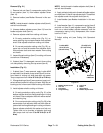
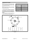
IMPORTANT: Over tightening reel bearing adjuster
nut may damage reel bearings.
11.Makesurethatset screw(item21)is looseinLH side
plate to allow bearing adjuster nut movement. With the
cutting unit and reel in a horizontal position, torque the
bearing adjuster nut (item 20) 25 in--lb (2.8 N--m) to re-
move cutting reel end play.
12.Loosen the bearing adjuster nut. Then torque bear-
ing adjuster nut from 15 to 17 in--lb (1.7 to 1.9 N--m).
After torquing nut,checkthat reelrollingtorque doesnot
exceed 10 in--lb (1.1 N--m).
13.Apply Loctite #242 (or equivalent) to threads of set
screw(item 21)andsecure bearingadjusternut inplace
withsetscrew.Torque setscrewfrom12to15 in--lb(1.4
to 1.7 N--m).
14.Adjust cutting unit (see Cutting Unit Operator’s
Manual).
NOTE: The parallel position of the rear roller to the cut-
ting reel is controlled by the precision machined frame
and side plates of the cutting unit. If necessary, the cut-
ting unitside plates canbe loosened and aslight adjust-
ment can be made to parallel the rear roller with the
cutting reel(see Leveling Rear Rollerin the Set--Up and
Adjustments section of this Chapter).
15.If cutting unit is equipped with optional groomer or
rear rollerbrush, install componentsfor those optionsto
left hand side plate of cutting unit. See Service and Re-
pairs section of Chapter 8 -- Groomer for information on
groomer. See Rear Roller Brush in the Service and Re-
pairs sectionof thischapter forinformation on rearroller
brush.
16.If counterweight was removed from cutting unit,
install new o--r ing (item 12) on counter weight. Secure
counter weight to cutting unit side plate with two (2) cap
screws. Torque screws from 27 to 33 ft-lbs (37 to 44
N--m).
17.Lubricate cutting unit grease fittings until grease
purges from relief valves in side plates. Initial greasing
may require several pumps of a hand grease gun.
18.Install cutting unit to the machine.