


Greensmaster eFlex 1800/2100Page 4 -- 40Electrical System
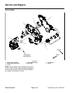
Main Contactor
Greensmaster eFlex machines use the main contactor
to connect the lithium battery pack and the electric mo-
tor. The contactor is energized by the TEC controller.
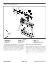
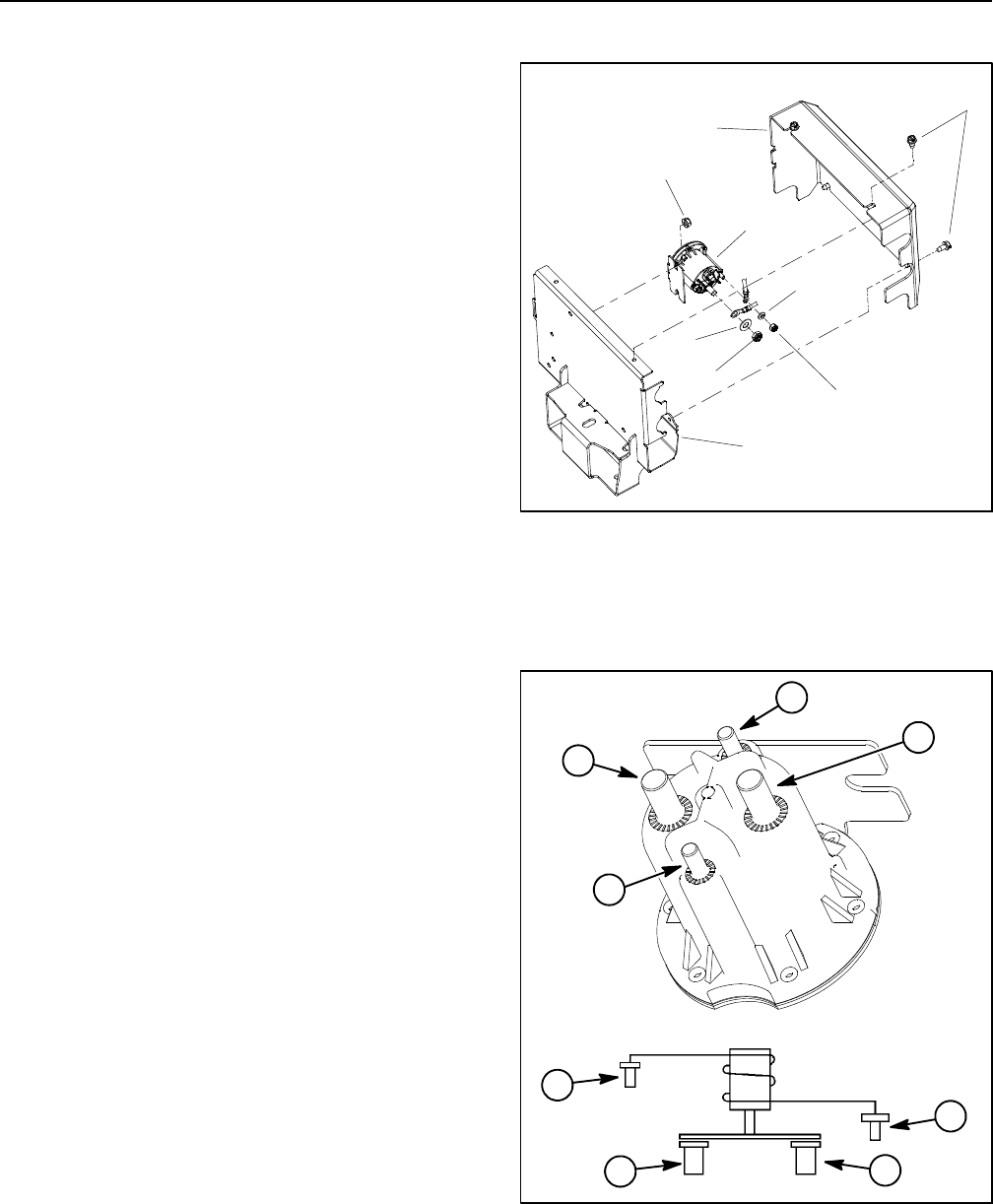
The contactor is attachedto the machine under thepow-
er center cover (Fig. 51).
NOTE: When the key switch is turned to the START
position, the contactor inside the battery pack will be en-
ergized followed shortly by the main contactor being en-
ergized. There should be an audible click as each of
these contactors are energized.
NOTE: A faulty main contactor may cause a #4 fault to
be generated and displayed on the InfoCenter. Refer to
InfoCenter Display in this chapter for information on
faults.
Main Contactor Testing
1. Park machine on level surface and place traction le-
ver in the NEUTRAL position. Turn key switch to the
OFF position and remove key from the switch. Discon-
nect the battery pack (see Lithium Battery Pack Con-
nection in the General Information section of this
chapter).
2. Remove two (2) screws that secure rear of power
center cover to m achine (Fig. 51). Then, loosen upper
two (2) screws on cover. Carefully remove cover from
machine.
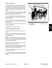
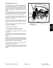
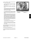
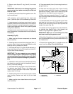
3. Make sure that battery pack is disconnected. Use a
multimeter to measure resistance across the contactor
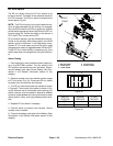
postsasfollows(Fig.52):
A. Resistance across the main contact posts should
be infinite ohms.
B. Resistance across the coil posts should be
approximately 195 ohms.
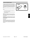
4. The machine wire harness connector for work lights
canbeusedtoaccessagroundconnectionformain
contactor voltage testing:
A. Locate the wire harness connector for work lights
located on left side of upper handle. The connector
will be identified with a tag and will have a pink and a
black wire attached to the connector.
B. Remove plug or work light harness connector (if
machine is equipped with optional work lights) from
machine wire harness work light connector.
C. The machine wire harness work light connector
leadingto the harness black wirewillbe used for con-
tactor voltage testing.
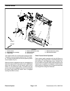
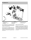
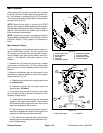
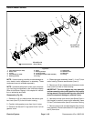
1. Power center cover
2. Screw (4 used)
3. Rear base
4. Contactor
5. Flange nut (2 used)
6. Flat washer (2 used)
7. Lock nut (2 used)
8. Flat washer (2 used)
9. Lock nut (2 used)
Figure 51
3
2
1
4
5
8
6
9
7
1. Main contact post 2. Coil post
Figure 52
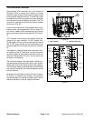
WIRING
DIAGRAM
1
2
1
1
2
2
2
1