


Greensmaster eFlex 1800/2100 GroomerPage 7 -- 17
Grooming Reel Service
Inspect grooming reel blades frequently for damage and
wear. Straighten bent blades with a pliers. Replace
blades that are worn or damaged.
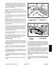
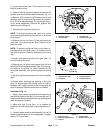
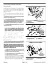
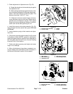
Carbide tipped g rooming blades (Fig. 16) should be re-
placed if the carbide tip is worn, loose or missing. Also,
if the blade is eroded around the carbide insert, the
blade should be replaced.
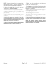
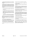
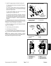
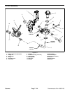
Grooming blades without a carbide tip (Fig. 17) should
be replaced if worn or damaged. Blades without a car-
bide tip that are rounded to the midpoint of the blade tip
can be reversed on the grooming shaft to extend the life
of the blade.
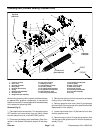
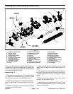
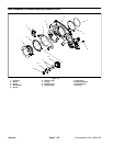
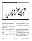
Disassembly (Fig. 15)
1. Removegrooming reel from cutting unit(seeGroom-
ing Reel Removal (Forward Rotating or Counter Rotat-
ing) in this section).
2. Remove lock nut from either end of the shaft (Fig.
15).
IMPORTANT: If grooming reel is equipped with car-
bide tipped blades, note position of blades on
groomer shaft as they are removed. Correct direc-
tion of blades is required for proper groomer opera-
tion.
3. Remove spacers and blades from groomer shaft as
necessary.
Assembly (Fig. 15)
1. Start by placing thick spacer against the lock nut
installed on one end of groomer shaft. Then, place first
blade against installed spacer (Fig. 15).
IMPORTANT: If groomer is equipped with blades
with carbide tips, make sure that blades are
installed with the tips in the same, correct direction.
2. For 1 /2 inch (1.3 cm) blade spacing, make sure there
are two (2) blade spacers between blades (Fig. 15).
3. When all blades have been installed, place second
thick spacer on shaft and then thread second lock nut
onto the shaft.
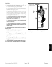
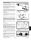
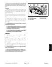
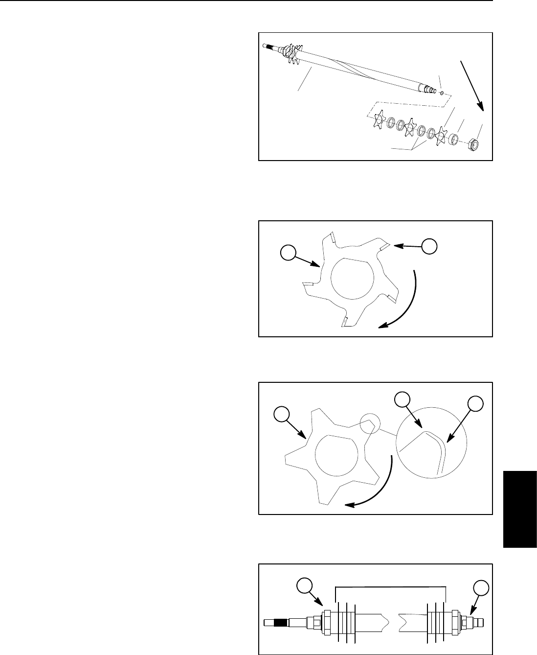
4. Position lock nuts to allow blades and spacers to be
centered on the shaft (Fig. 18). Torque lock nuts from
200 to 250 in--lb (23to 28 N--m) so spacers a re not free
to rotate.
5. Install grooming reel back onto cutting unit (see
Grooming Reel Installation (Forward Rotating or Count-
er Rotating) in this section).
1. Grooming reel shaft
2. Groomer blade
3. Blade spacer
4. Thick spacer (2 used)
5. Lock nut (2 use d)
6. O--ring
Figure 15
3
2
4
1
5
6
200 to 250 in--lb
(23to28N--m)
1. Grooming blade 2. Carbide tip
Figure 16
ROTATION
1
2
1. Grooming blade
2. Sharp edge
3. Dull (rounded) edge
Figure 17
ROTATION
3
2
1
1. Lock nut 2. Grooming shaft
Figure 18
CENTER BLADES ON SHAFT
2
1
Groomer