


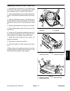
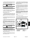
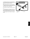
Greensmaster eFlex 1800/2100 Page 6 -- 13 Cutting Unit
7. Remove two (2) bedbar pivot bolts (item 18), four (4)
metal washers (item 17) and four (4) plastic washers
(item 16) from the cutting unit side plates.
CAUTION
Contact with the reel, bedknife or other cutting
unit parts can result in personal injury. Use
heavy gloves when handling the bedbar.
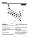
8. Remove bedbar assembly from cutting unit.
9. Inspect nylon bushings (item 15) and rubber bush-
ings (item 14) in side plates for wear or damage. Re-
move bushings and replace if necessary.
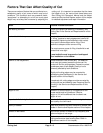
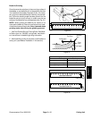
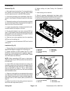
Bedbar Installation (Fig. 17)
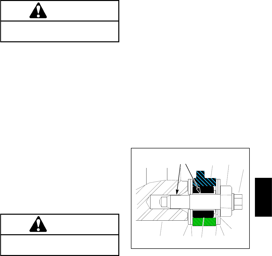
1. If rubber bushing was removed from either cutting
unit side plate, apply grease to outside surface of new
bushing and install into side plate. The bushing should
be installed flush with the inside of the side plate (Fig.
18).
2. If removed, install the nylon bushings (item 15) with
flange facingoutward. Applyantiseize lubricant to inside
of flange bushing.
3. Apply antiseize lubricant to the bedbar threads and
the shoulder area of each bedbar pivot bolt (Fig. 18).
IMPORTANT: When installing washers (items 16
and 17), make sure that plastic washers are posi-
tioned on either side of t he cutting unit sideplate
(Fig. 18).
4. Slideone (1) metal washer (item 17) and then one (1)
plastic washer (item 16) onto each bedbar p ivot bolt.
CAUTION
Contact with the reel, bedknife or other cutting
unit parts can result in personal injury. Use
heavy gloves when handling the bedbar.
5. Position bedbar into cutting unit. Make sure that the
top of each bedbar arm is between washer (item 11) and
adjuster screw flange (item 4).
6. Position one (1) metal washer (item 17) and one (1)
plastic washer (item 16) between bedbar and each cut-
ting unit side plate (Fig. 18).
7. Install the bedbar pivot bolt assemblies. Make sure
that plastic washers are not caught on the threads of the
pivot bolts. Torque each bedbar pivot bolt from 190 to
240 in--lb (22 to 27 N--m).
8. Tighten both lock n uts ( item 10) until outside wash-
ers do not have any endplay but still can be rotated. Do
not over tighten the lock nuts as this can distort the side
platesand affectreel bearing adjustment. When the lock
nut is correctly tightened, there may be a gap at the in-
side washers.
9. Tighten the lock nut (item 13) on each bedbar adjust-
er assembly until the adjuster spring is fully com-
pressed, then loosen lock nut 1/2 turn.
IMPORTANT: When adjusting bedknife to cutting
reel, make sure that contact is as light as possible
to lengthen the amount ofwork themachinewillper-
form on each charge.
10.Adjust cutting unit (see Cutting Unit Operator’s
Manual).
11.Install cutting unit to machine.
12.After all necessary adjustments have been made,
connect the battery pack (see Battery Pack Connection
in the General Information section of this chapter).
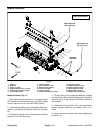
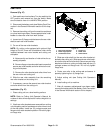
1. Cutting unit sideplate
2. Rubber bushing
3. Nylon bushing
4. Plastic washer
5. Metal washer
6. Bedbar
7. Bedbar pivot bolt
8. Loc k nut
Figure 18
1
2
3
4
6
7
8
5
4
Antiseize
Lubricant
5
Cutting Unit