Greensmaster eFlex 1800/2100Page 6 -- 22Cutting Unit
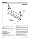
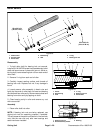
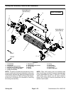
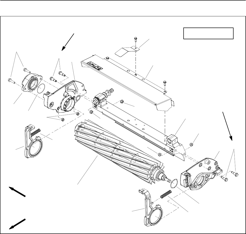
Cutting Reel Assembly Removal and Installation
1. Crossmember
2. LH side plate
3. Compression spring (2 used)
4. Shoulder bolt (2 used per side plate)
5. Flange nut (2 used per side plate)
6. Cutting reel assembly
7. RH pitch arm
8. Flange head screw (2 used)
9. RH side plate
10. Weight
11. Hex nut
12. O--ring
13. Grass shield
14. Flat wire spring
15. LH pitch arm
16. Sensor target plate
Figure 34
FRONT
RIGHT
210 to 240 in--lb
(24to27N--m)
4
2
9
5
13
1
4
5
5
5
7
11
3
210 to 240 in--lb
(24 to 27 N--m)
6
14
8
10
12
3
15
16
eFlex2100Shown
NOTE: This section provides the procedure for remov-
ing and installing the cutting reel assembly (cutting reel,
flocked seals, reel bearings,bearing lock screwand reel
nut) from the cutting unit. Refer to Cutting Reel Assem-
bly Service in this section for information on servicing
the cutting reel assembly.
NOTE: EFlex 2100 cutting units use shoulder bolts
(item 4)and flangenuts (item 5) tosecure theside plates
to the crossmember as shown in Figure 34. On eFlex
1800 cutting units, square nuts are used instead of
flange nuts. Cutting unit service procedures are the
same on both models.


