


Greensmaster eFlex 1800/2100 Page 4 -- 47 Electrical System
8. Remove and discard O--ring (item 8) from motor
housing.
IMPORTANT: Make sure to not damage the gearbox
cover counter bore when removing the shaft seal
from the cover.
9. Carefully remove shaftseal from gearbox cover. Dis-
card removed seal.
10.If necessary, remove bearings from output gear
(item 11) and rotor (item6).Discardbearingsifremoved.
11.Inspect grease in output gear area of motor housing.
If grease is clean and not contaminated, it can remain in
housing. If grease is contaminated, clean grease from
housing and replace with 15ml of NLGI grade 00 grease
during motor assembly.
12.Inspect motor components for wear or damage. Re-
place components or complete electric motor assembly
if necessary.
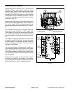
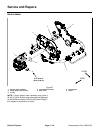
Assembly (Fig. 58)
1. Make sure that all motor components are cleaned
before assembly.
2. If bearings were removed from output gear (item 11)
and rotor (item 6) install new bearings. Make sure that
bearings are fully pressed onto shafts.
3. Lubricate new inner O--ring (item 8) with dielectric lu-
bricant (see Special Tools in this chapter) and install O--
ring into rear of motor housing.
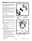
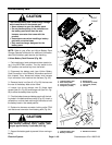
IMPORTANT: The rotor magnets are very powerful
and can cause the rotorto shift position very rapidly
during installation. Be cautious during rotor install-
ation to prevent component damage or personal in-
jury.
4. Use electric motor rotor tool set (see Special Tools in
this chapter) to carefully install rotor assembly (items 5,
6 and 7) into motor housing.
5. Lubricate new O--rings (items 14 and 3) with dielec-
tric lubricant (see Special Tools in this chapter) and
install O--rings to grooves in motor cover. Place wave
washer (item 4) in cover.
6. Carefully slide motor cover onto r otor until it contacts
motor housing. Secure cover with six (6) torx head
screws.
7. Make sure that rotor rotates before continuing with
motor a ssembly.
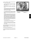
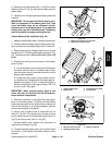
8. Placewavewasher(item 4) into housing bore for out-
put gear bearing.
9. Make sure that output gear area of motor housing
has clean grease remaining in housing. If grease was
cleaned from housing, install 15ml of new NLGI grade
00 grease into housing during motor assembly.
10.Slide output gear assembly (items 5, 11 and 7) into
front of housing. Make sure that output gear teeth mesh
with rotor gear.
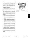
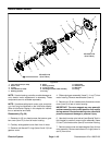
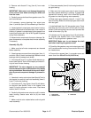
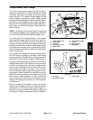
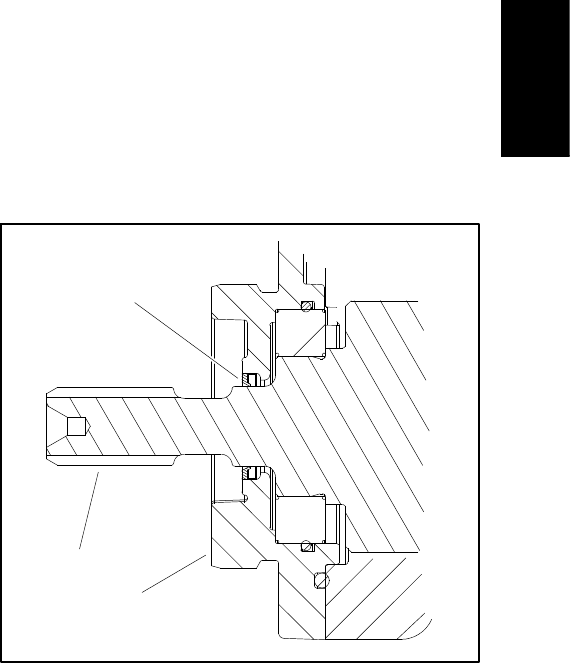
11.Install shaft seal (item 13) into gearbox cover. Press
shaft seal into front cover until it is flush with the cover
surface. Shaft seal should have the seal lip toward the
inside of the motor (Fig. 59).
12.Lubricate new O--rings (items 8 and 10) with dielec-
tric lubricant (see Special Tools in this chapter) and
install O--rings to grooves in gearbox cover.
IMPORTANT: Make sure to not damage the shaft
seal when installing the gearbox cover.
13.Carefully slide gearbox cover onto output gear s haft
until it contacts motor housing. Secure cover with six (6)
torx head screws.
14.Torque all torx screws (item 1) on gearbox cover and
motor cover from 35 to 45 in--lb (4 to 5 N-- m).
1. Output gear
2. Gearbox cover
3. Shaft seal
Figure 59
3
2
1
Electrical
System