


Greensmaster eFlex 1800/2100 Traction and Reel Drive SystemPage 3 -- 39
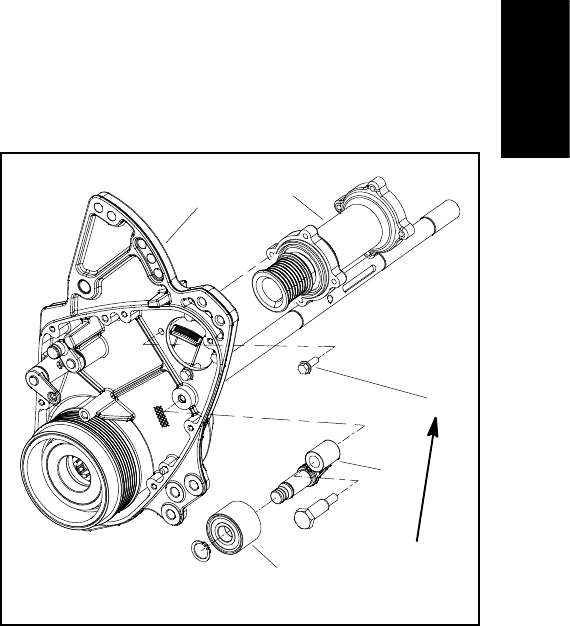
7. If it is necessary to remove extension housing (item
2):
A. Loosen fasteners (items 12, 11 and 13) that se-
cure transmission housing to machine frame.
B. Remove four (4) washer head screws that secure
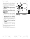
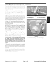
extension housing to transmission housing.
C. Remove four (4) washer head screws that secure
extension housing to RH drum drive housing (Fig.
46).
D. Carefully shift position of transmission housing to
allow removal of the extension housing.
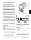
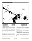
Assembly (Fig. 45)
1. If extension housing was removed:
A. Position the extension housing between trans-
mission housing and RH drum drive housing.
B. Align extension housing with RH drum d rive
housing. Install four (4) washer h ead screws finger
tight to hold extension housing in position.
C. Position transmission housing to the extension
housing. Install four (4) washer h ead screws finger
tight to hold extension housing in position.
D. Secure extension housing to transmission hous-
ing and RH drum drive housing with washer head
screws. First, torque all washer head screws from 15
to 40 in--lb(1.7to4.5N--m). Then, using an alternat-
ing crossing pattern, torque all screws from 85 to 95
in--lb (9.6 to 10.7 N--m).
E. Secure transmission housing to machine frame
by tightening fasteners (items 12, 11 and 13). If fas-
teners were removed, make sure that washer (item
5) is below frame tube.
2. If removed, slide wave washer (item 8), spacer (item
7) and ball bearings (item 3) into extension housing.
3. Slide shaft of traction drum drive driven pulley (item
4) through extension housing bearings and spacer.
4. Apply antiseize lubricant to pulley surface of drum
drive driven pulley (item 4).
5. Install woodruff key (item 9) in shaft and slide driven
pulley (item 6) onto shaft. Secure pulley (item 6) with
hardened washer (item 5) and flange head screw (item
12).
6. Install drum drive belt to machine (see Drum Drive
Belt in this section).
7. Install transmission drive belt and all machine com-
ponents removed for drum drive system service (see
Transmission Drive Belt in this section).
8. Connectthe battery pack(see Battery Pack Connec-
tion in the General Information section of this chapter).
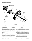
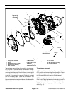
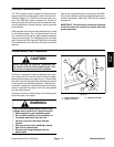
1. RH drum drive housing
2. Extension housing assy
3. Screw (4 used)
4. Idler arm assembly
5. Idler pulley assembly
Figure 46
See text for
tightening
procedure
1
2
3
4
5
Traction and Reel
Drive System