


Greensmaster eFlex 1800/2100 Traction and Reel Drive SystemPage 3 -- 13
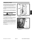
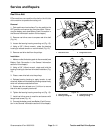
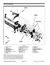
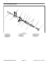
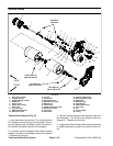
Reel Drive Assembly Removal (Fig. 16)
1. Parkmachineonlevelsurface.Turnkeyswitchtothe
OFF position and remove key from the switch. Discon-
nect the battery pack (see Battery Pack Connection in
the General Information section of this chapter).
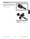
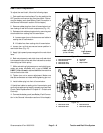
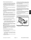
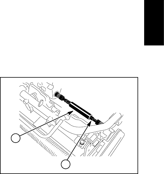
2. Slide the telescoping coupler off the cutting unit hex
shaft (Fig. 17).
3. Remove reel drive belt (see Reel Drive Belt Replace-
ment in this section).
4. Loosen two (2) set screws (item 23) that secure reel
pulley (item 8) to reel drive shaft (item 7). Slide pulley
from drive shaft. Locate and retrieve woodruff key (item
22) from shaft.
5. Remove washer head screw (item 4) that secures
reel drive housing to cutting unit side plate.
NOTE: Hex nuts (item 6) have adhesive applied during
cutting unit production. The nuts should remain in cut-
ting unit side plate during reel drive housing removal.
6. Remove two (2) flange head screws (item 5) that se-
cure reel drive housing to cutting unit side plate.
7. Remove reel drive assembly from cutting unit.
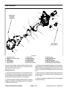
8. Remove components from reel drive housing as
necessary using Figure 16 as a guide.
A. Ifidler shaft bearings (item 24) aretobe removed,
use press to remove bearings and bearing spacer
from shaft. Discard bearings after removal.
NOTE: See Reel Drive Bearing Housing in this section
for disassembly and assembly information of bearing
housing assembly (item 12).
NOTE: Reel pulleys (items 8, 11 and 14) can be identi-
fied by color and number of teeth. Pulley location can
vary based on desired cutting unit clip frequency (see
Cutting Unit Clip Adjustment in the Adjustments section
of this chapter).
Reel Drive Assembly Installation (F ig. 16)
1. Install all removed components to reel drive housing
using Figure 16 as a guide.
A. If bearings (item 24) were removed from idler
shaft, use press to install bearings and bearing
spacer onto shaft.
2. Apply light coating of grease on reel drive housing
O--rings (items 2 and 9).
3. Position reel drive assembly to cutting unit. Make
sure that spring pin (item 21) and compression spring
(item 16) are positioned between reel d rive housing and
bearing housing assembly.
4. Secure reel drive assembly with two (2) flange head
screws (item 5) and washer head screw (item 4).
5. Install woodruff key (item 22) t o reel d rive shaft (item
7). Apply antiseize lubricant to top of key.
6. Slide reel pulley (item 8) onto reel drive shaft until it
contacts shoulder on shaft . Secure reel pulley with two
(2) set screws (item 2 3). Torque set screws from 60 to
65 in--lb (6.8 to 7.3 N--m).
7. Install reel drive belt (see Reel Drive Belt Replace-
ment in this section). Make sure that reel drive cover is
securedtohousingafterbeltinstallation.
8. Slide the telescoping coupler onto the cutting unit
hex shaft (Fig. 17).
9. Connectthe battery pack(see Battery Pack Connec-
tion in the General Information section of this chapter).
1. Telescoping coupler 2. Cutting unit hex shaft
Figure 17
1
2
Traction and Reel
Drive System