


Greensmaster eFlex 1800/2100 Page 6 -- 19 Cutting Unit
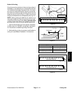
Rear Roller
Removal (Fig. 27)
1. Parkmachineonlevelsurface.Turnkeyswitchtothe
OFF position and remove key from the switch. Make
sure the traction lever is in the NEUTRAL position.
2. Disconnect the b attery pack (see Battery Pack Con-
nection in the General Information section of this chap-
ter).
3. Remove the cutting unit from the machine and place
onalevelworkingsurface.Place support blocks under
bedbar to raise rear roller from work surface.
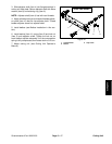
4. Loosen two (2) flange nuts that secure the rear roller
shaft to each rear roller bracket.
5. On one of the rear roller brackets:
NOTE: On cutting units equipped with optional High
Height of Cut Kit, t here will be additional roller shims
installed between rear roller bracket and cutting unit
side plate.
A. Note quantity and location of roller shims for as-
sembly purposes.
B. Remove flange nuts and socket head screws that
secure rear roller bracket and roller shims to the cut-
ting unit side plate.
C. Remove the roller bracket and roller shims from
the rear roller and cutting unit.
6. Slide the rear roller assembly from the remaining
rear roller bracket on the cutting unit.
7. If necessary, remove the second rear roller bracket
and roller shims from the cutting unit.
Installation (Fig. 27)
1. Place cutting unit on a level working surface.
NOTE: Refer to Cutting Unit Operator’s Manual for
number of roller shims required for various height of cut
settings.
2. If both rear rollerbrackets wereremoved fromcutting
unit side plate, position brackets and roller shims to one
of the side plates. Install two (2) carriage screws and
flange nutsto retain bracketin position. Do notfully tight-
en flange nuts.
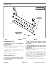
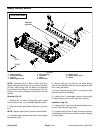
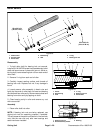
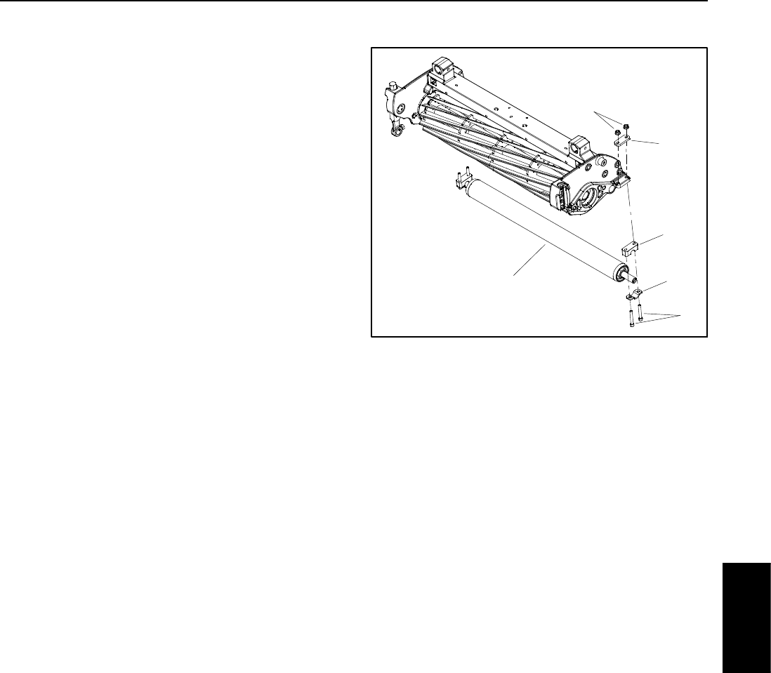
1. Rear roller assembly
2. Roller height spacer
3. Socket head screw
4. Flange nut
5. Roller shim
6. Shaft retainer
Figure 27
1
2
3
4
5
6
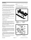
3. Slide rear roller shaft into the rear roller bracket at-
tached to the cutting unit. Slide second rear roller brack-
et onto the other end of roller shaft. Secure second roller
bracket and shims to cutting unit side plate with two (2)
carriage screws and flange nuts. Do not fully tighten
flange nuts.
4. Center rear roller to the cutting reel and secure in
place by tightening four (4) flange nuts.
5. Adjust cutting unit (see Cutting Unit Operator’s
Manual).
6. Install cutting unit to machine.
7. After all necessary adjustments have been made,
connect the battery pack (see Battery Pack Connection
in the General Information section of this chapter).
Cutting Unit