


Greensmaster eFlex 1800/2100Groomer Page 7 -- 14
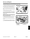
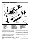
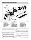
Grooming Reel (Counter Rotating Groomer Drive)
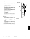
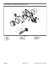
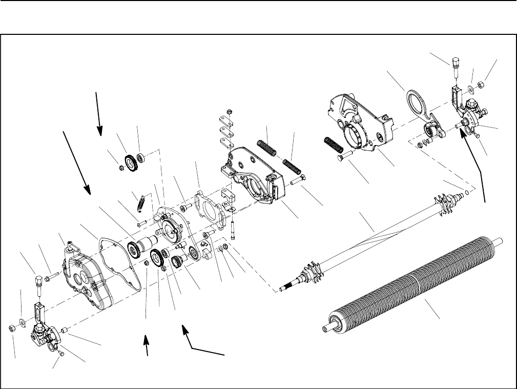
Figure 11
1. RH groomer arm assembly
2. HOC nut (2 used)
3. Bushing (2 used)
4. Spring washer (2 used)
5. Lock nut (2 used)
6. LH groomer arm assembly
7. Cap screw (2 used)
8. Grooming reel assembly
9. HOC washer (2 used)
10. HOC screw (2 used)
11. O--ring
12. RH drive plate assembly
13. Shoulder bolt (2 used)
14. Driven gear (30T)
15. Lock nut
16. Front roller
17. Groomer drive gear (45T)
18. Bearing (2 used)
19. RH cutting unit side plate
20. Gasket
21. Flange head screw (5 used)
22. Groomer cover assembly
23. 47T idler gear
24. Flange nut (2 used)
25. Extension spring
26. Inner spring (2 used)
27. Outer spring (2 used)
28. LH support plate assembly
29. Support plate
30. Button head screw (4 used)
31. Plow bolt (2 used)
32. LH cutting unit side plate
33. 43T idler gear
33
1
3
4
5
6
7
9
10
12
13
14
15
17
18
20
21
22
23
24
25
26
27
28
29
30
31
32
7
13
18
24
9
10
2
2
8
16
11
19
125 ft--lb
(170 N--m)
120 in--lb
(13.5 N--m)
120 in--lb
(13.5 N--m)
17 to 21 ft--lb
(23 to 28 N--m)
Antiseize
Lubricant
31
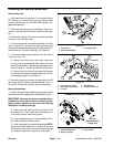
Remove the grooming reel to replace individual blades,
to replace worn groomer components, to reverse the
blades on the shaft (if not equipped with carbide blades)
or to replace the grooming shaft.
Removal (Fig. 11)
1. Parkmachineon level surface. Turnkeyswitch to the
OFF position and remove key from the switch. Make
sure the traction lever is in the NEUTRAL position.
2. Disconnect the battery pack (see Battery Pack Con-
nection in the General Information section of this chap-
ter).
3. Remove the cutting unit from the machine and place
cutting unit on a flat work area.
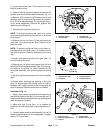
4. Make sure that handle on groomer cover is rotated
toward front of machine so that groomer drive is en-
gaged.
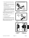
5. Removegroomer cover assembly (item22) and gas-
ket (item 20)from machine (see Groomer Cover(Count-
er Rotating Groomer Drive) in this section). Discard
gasket.
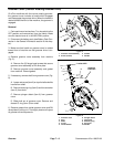
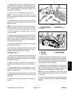
6. Carefully remove extension spring from anchor
points on RH drive plate (Fig. 12).
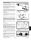
7. Remove the two (2) idler gears (43T and 47T) from
the RH drive plate assembly (Fig. 13). The bearings are
pressed into the gears.