


Greensmaster eFlex 1800/2100Groomer Page 7 -- 22
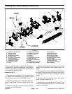
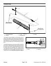
Idler Assembly (Counter Rotating Groomer Drive)
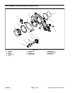
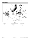
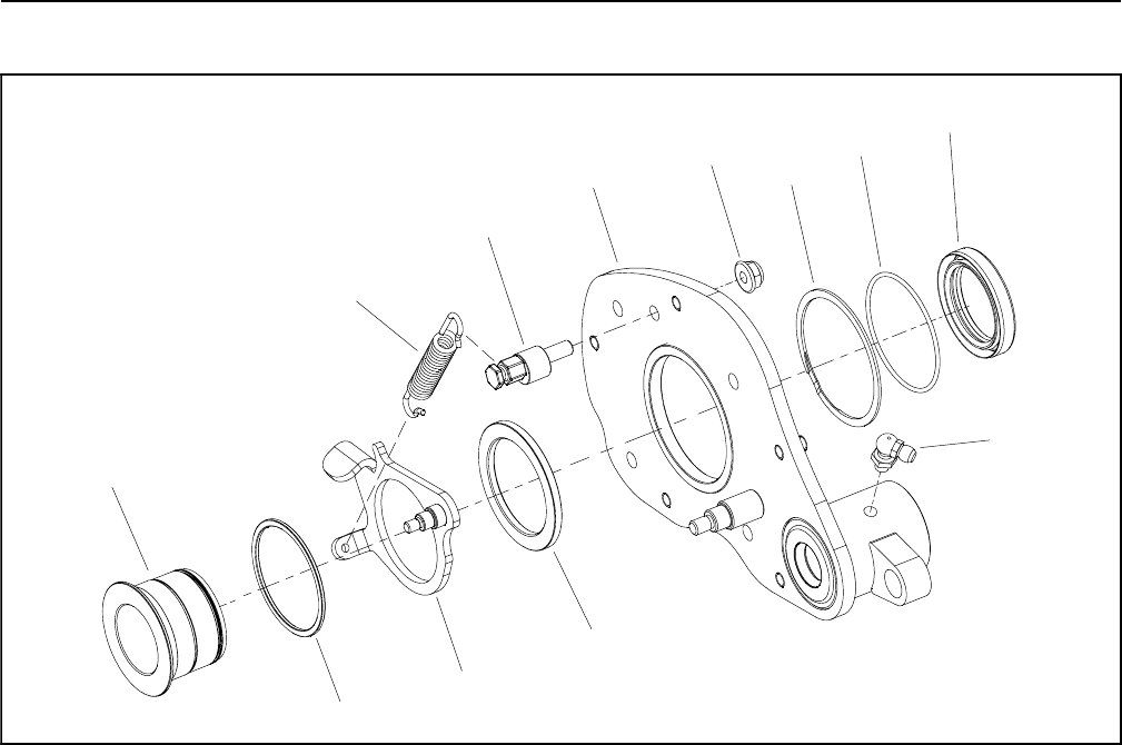
Figure 27
1. RH drive plate
2. Adjustment cam
3. Spacer
4. Idler bracket
5. Spacer
6. Reel hub
7. Retaining ring
8. O--ring
9. Flange nut
10. Extension spring
11. Grease fitting
12. Grease seal
6
3
5
4
12
9
7
8
10
1
2
11
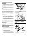
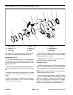
The groomer RH drive plate assembly incorporates the
idler system for engaging the groomer gear drive.
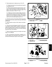
Disassembly (Fig. 27)
1. Parkmachineon level surface. Turnkeyswitch to the
OFF position and remove key from the switch. Make
sure the traction lever is in the NEUTRAL position. En-
gage parking brake.
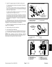
2. Disconnect the battery pack (see Battery Pack Con-
nection in the General Information section of this chap-
ter).
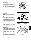
3. Make sure that handle on groomer cover is rotated
toward front of machine so that groomer drive is en-
gaged.
4. Remove groomer cover assembly and gasket from
machine (see Groomer Cover (Counter Rotating
Groomer Drive) in this section).
5. Remove RH drive plate assembly from right side of
cutting unit (see Grooming Reel (Counter Rotating
Groomer Drive) in this section).
6. Using Figure 27 as a guide, remove idler compo-
nents from RH drive plate as needed.
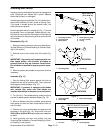
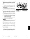
Assembly (Fig. 27)
1. Assemble idler components to RH drive plate using
Figure 27 as a guide. Make sure that retaining ring (item
7) is fully seated in groove of reel hub after assembly.
NOTE: When properly installed, the idler bracket ( item
4) should pivot freely on reel hub.
2. Install RH drive plate assembly to right side of cutting
unit (see Grooming Reel (Counter Rotating Groomer
Drive) in this section). Make sure that groomer drive
gear and grooming reel driven gear are properly
torqued. Do not install idler gears, extension spring or
groomer cover assembly to drive plate assembly.