


Greensmaster eFlex 1800/2100 Page 4 -- 29 Electrical System
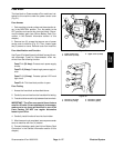
Key Switch
The key switch allows machine operation to be turned
on and off. The key switch has three (3) positions: OFF,
RUN and START. This switch is one of several inputs for
the TEC controller and is located on the console on the
handle (Fig. 35).
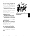
Check key switch operation with the InfoCenter on the
console. With the key switch in the RUN position, the In-
foCenter should allow the information screen to be dis-
played. With the InfoCenter in the Diagnostics menu,
choose Key Start and make sure that the switch state
changes as the key switch is moved to START and is
then released. If the InfoCenter operation suggests a
faulty key switch, proceed to key switch testing below.
NOTE: If the eFlex machine is sitting idle for five (5)
minutes with the key switch in the RUN position, the ma-
chine will shut off.
NOTE: A faulty key switch may cause a #12 fault to be
generated and displayed on the InfoCenter. Refer to In-
foCenter Display in thischapter for information on faults.
Key Switch Testing
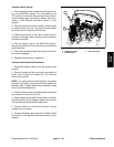
1. Park machine on level surface and place traction le-
ver in the NEUTRAL position. Turn key switch to the
OFF position and remove key from the switch. Discon-
nect the battery pack (see Lithium Battery Pack Con-
nection in the General Information section of this
chapter).
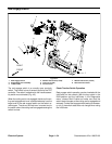
2. Remove console cover from handle to allow access
to key switch (Fig. 35).
3. Disconnect wire harness electrical connector from
the key switch.
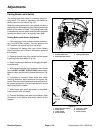
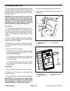
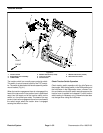
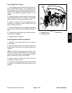
4. With the use of a multimeter (ohms setting), the
switch functions may be tested to determine whether
continuity exists between the various terminals for each
switch position. The switch terminals are marked as
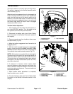
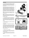
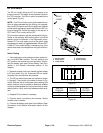
shown in Figure 36. The circuitry of the on/off switch is
shown in the chart in Figure 37. Verify continuity be-
tween switch terminals.
5. Replace key switch if necessary.
6. When switch testing is complete, connect wire har-
ness electrical connector to the key switch. Install con-
sole cover to handle.
7. Connect the battery pack (see Lithium Battery Pack
Connection in the General Information section of this
chapter).
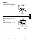
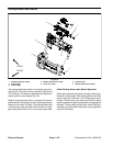
1. Key switch
2. Switch panel
3. Lower handle
4. Console cover
5. Screw (4 used)
Figure 35
5
3
1
2
4
FRONT
RIGHT
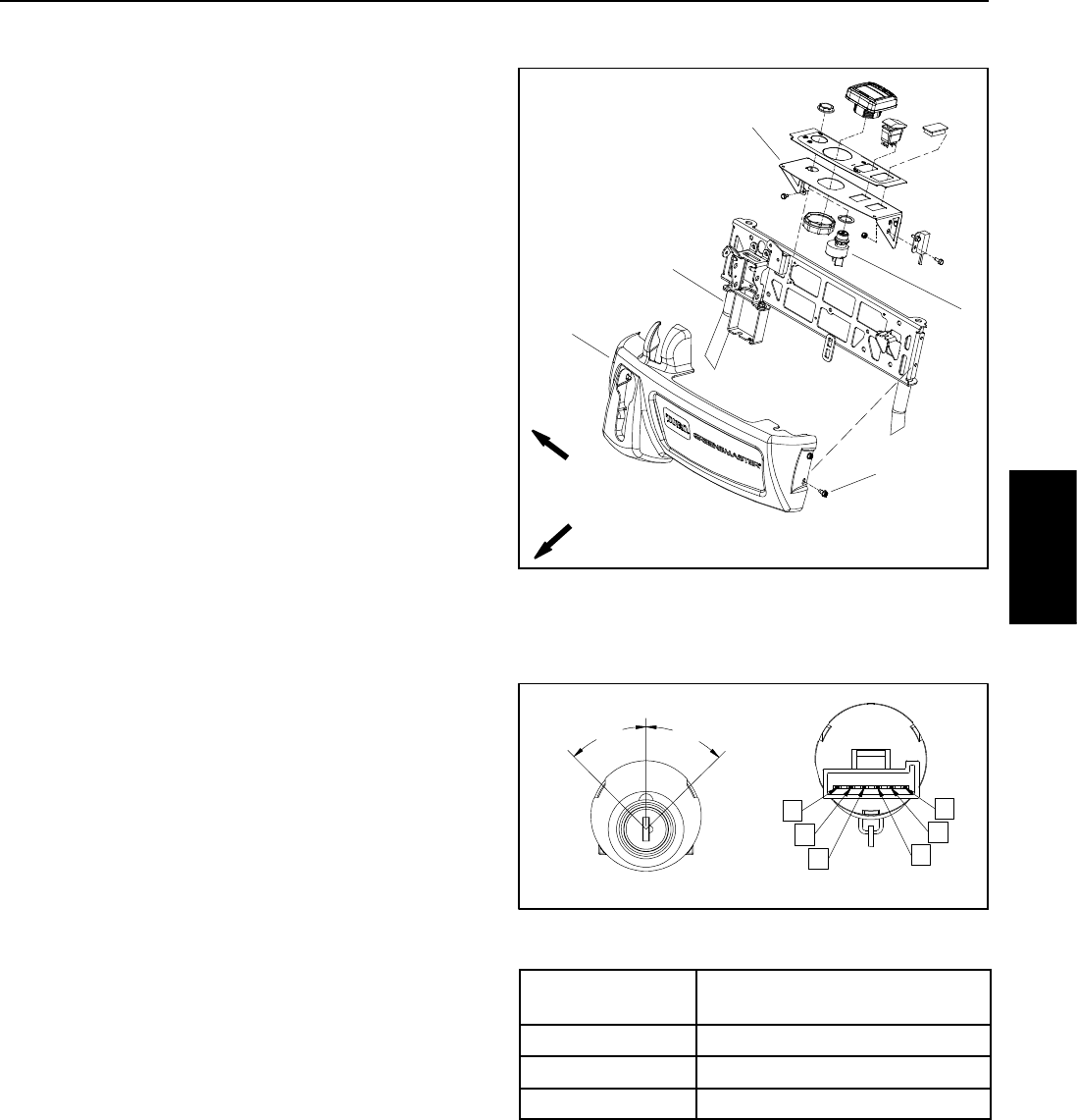
Figure 36
REAR VIEW
FRONT VIEW
A
B
C
D
E
F
START
OFF
RUN
45
o
45
o
SWITCH
POSITION
CIRCUITS
OFF NONE
RUN B+C+F, D+E
START A+B+C
Figure 37
Electrical
System