Greensmaster eFlex 1800/2100 Traction and Reel Drive SystemPage 3 -- 29
8. Remove transmission belt from drive and idler pul-
leys in transmission.
9. Check condition of all pulleys and idler components.
10.Clean inside of transmission before installing new
belt.
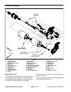
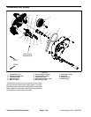
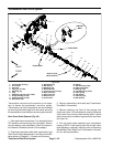
Drive Belt Installation (Fig. 34)
IMPORTANT: During assembly, make sure that
transmission cover is installed with fasteners prop-
erly torqued before applying tension to transmis-
sion belt.
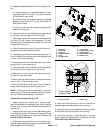
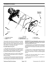
1. Install new transmission belt onto pulleys in trans-
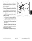
mission. Make sure that belt is correctly routed around
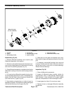
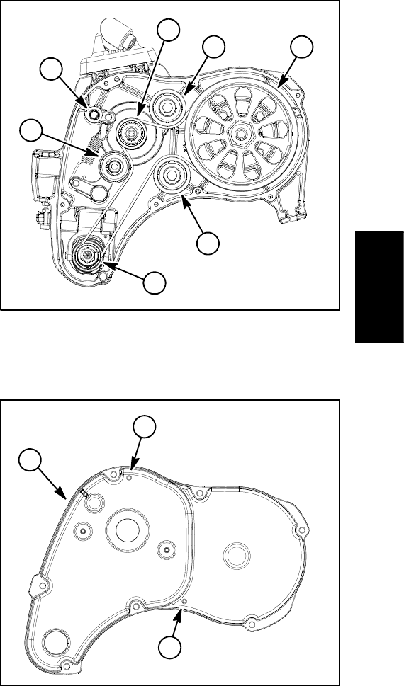
drive and idler pulleys (Fig. 35).
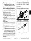
2. Make sure that wave washers (item 4) are pressed
into bearing bores of transmission cover. Also, m ake
sure that two (2) dowel pins are pressed into bores in the
transmission housing.
3. Position new gasket to transmission assembly. Align
gasket to two (2) dowel pins in transmission housing.
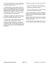
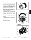
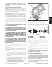
4. Install transmission cover. If necessary, use a rubber
mallet at dowel locations (Fig. 36) to seat cover to trans-
mission.
5. Install seven (7) washer head screws to secure cov-
er to transmission. Tighten screws as follows:
A. First, using an alternating crossing pattern,
torque all screws from 15 to 40 in--lb (1.7 to 4.5
N--m).
B. Again using an alternating crossing pattern,
torque all screws from 85 to 95 in--lb (9.6 to 10.7
N--m).
6. Apply tension to transmission belt by rotating the en-
gage/disengage shaft counter--clockwise (see Trans-
mission Belt Tensioner in the General Information
section of this chapter).
7. Slide telescoping coupler onto transmission shaft so
that drive shaft wire engages hex shaft on transmission.
Make sure that telescoping coupler is properly attached
to cutting unit hex shaft.
8. Install battery pack to machine (see Battery Pack in
the Service and Repairs section of Chapter 4 -- Electrical
System).
9. Connectthe battery pack(see Battery Pack Connec-
tion in the General Information section of this chapter).
1. Engage/disengage shaft
2. Drive pulley
3. Reel clutch pulley
4. Idler pulley
5. Drum drive pulley
6. Idler pulley
Figure 35
1
2
3
4
4
5
6
1. Transmission cover 2. Dowel location
Figure 36
1
2
2
Traction and Reel
Drive System


