


Greensmaster eFlex 1800/2100 Page 5 -- 9 Chassis and Controls
Installation
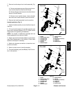
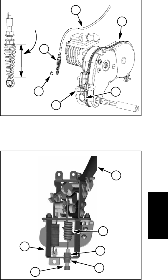
1. Secure reel clutch cable to traction lever assembly
(Fig. 9):
A. Install cable spring to spring anchor on lever as-
sembly. Orientatecablespring hook end toward front
of machine.
B. Slide the cable housing into the shift mount
bracket slot. Make sure that a jam nut, flat washer
and lock washer are on both sides of bracket. Adjust
jam nuts so that equal amount of cable threads are
visible above and below jam nuts. Leave jam nuts
snug until final cable adjustment.
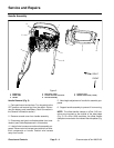
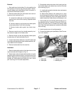
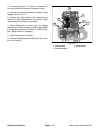
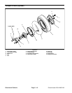
2. Route reel clutch cable to transmission and install
cable (Fig. 8):
A.Securecableeyelettotransmissionreelclutch
lever with retaining ring.
B. Position reel cable to the casting slot of transmis-
sion with a jam nut, flat washer and lock washer on
each side of the slot.
C. Adjust and tighten jam nuts to compress cable
spring to a length from 2.780”to 2.850”(70.6 to72.4
mm).
D. Remove rubber plug at front of transmission to
view reel clutch. Make sure that reel clutch teeth dis-
engage when the clutch is released. Also, verify that
clutch teeth do not bottom out when clutch is en-
gaged.
E. Secure reel drive cable to transmission bracket
with cable tie.
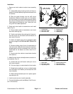
3. Make final reel clutch cable adjustment at traction le-
ver a ssembly (Fig. 9):
A. Loosen both top and bottom cable jam nuts at
shift mount bracket.
B. Pull down lightly on outer sheath of clutch cable.
C. Rotate bottom cable jam nut up on cable threads
until the bottom lock washer just contacts the shift
mount bracket.
D. While holding the bottom jam nut in place, tighten
top cable jam nut.
4. Install console cover to handle assembly.
5. Connectthe battery pack(see Battery Pack Connec-
tion in this section).
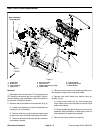
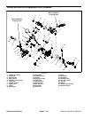
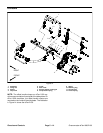
1. Transmission
2. Reel clutch cable
3. Reel clutch lever
4. Retaining ring
5. Cable spring
6. Rubber plug
Figure 8
2.780” to 2.850”
(70.6 to 72.4 mm)
1
3
2
4
5
6
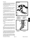
1. Shift handle
2. Reel clutch cable
3. Top cable jam nut
4. Bottom cable jam nut
5. Reel cable spring
6. Shift mount bracket
Figure 9
1
2
5
6
3
4
Chassis and
Controls