


Greensmaster eFlex 1800/2100 Page 5 -- 7 Chassis and Controls
Removal
1. Parkmachineonlevelsurface.Turnkeyswitchtothe
OFF position and remove key from the switch. Discon-
nect the battery pack (see Battery Pack Connection in
the General Information section).
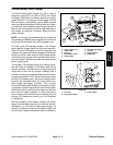
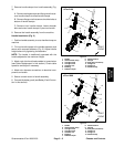
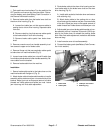
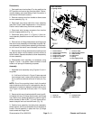
2. Remove brake cable from the brake lever shaft on
the drum drive housing (Fig. 6):
A. Loosen front cable jam nut that secures cable to
casting slot on drum drive housing. Separate cable
from slot.
B. Remove retaining ring that secures cable eyelet
to the brake shaft on drum drive housing.
C. Remove brake cable eyelet from brake lever
shaft.
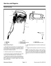
3. Remove console cover from handle assembly to al-
low access to upper end of brake cable.
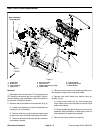
4. Remove flange nut that secures brake cable eyelet
to brake lever on machine handle (Fig. 5).
5. Loosen lower brake cable jam nut and lift cable free
from brake cable bracket onlowerhandle assembly. Re-
move cable from the bracket.
6. Remove brake cable from the machine.
Installation
1. Secure brake cable eyelet to the brake lever on the
machinehandlewithflangenut(Fig.5).
2. Attach brake cable to brake cable bracket on handle
assembly with a washer and jam nut on each side of the
bracket. Adjust jam nuts so t hat equal amount of cable
threads are visible above and below jam nuts. Leave
jam nuts snug until final cable adjustment.
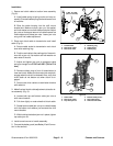
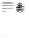
3. Route brake cable to the drum drive housing and se-
cure brake cable to the brake lever shaft on the drum
drive housing (Fig. 6):
A. Install cable eyelet to the brake lever and secure
with retaining ring.
B. Attach brake cable to the casting slot on drum
drive housingwith a washerand jam nuton each side
of the s lot. Adjust jam nuts so t hat equal amount of
cable threads are visible above and below jam nuts.
4. Adjust cable jam nuts at brake cable bracket on han-
dle assembly so that it requires 35 pounds (156 N) ap-
plied to the brake lever to release the parking brake
latch. After final cable adjustment, make sure that brake
does not drag.
5. Install console cover to handle assembly.
6. Connectthe battery pack(see Battery Pack Connec-
tion in this section).
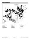
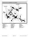
1. Brake cable
2. Cable eyelet
3. Cable jam nut location
4. Retaining ring
Figure 6
1
2
4
3
Chassis and
Controls