


Greensmaster eFlex 1800/2100 Traction and Reel Drive SystemPage 3 -- 33
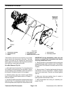
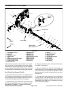
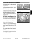
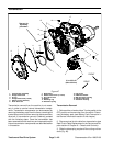
6. Inspect flange bushings and reel brake ring for wear
or damage (Fig. 40). Replace bushings and brake ring
if necessary.
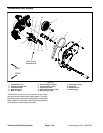
Reel Clutch Shaft Disassembly (Fig. 39)
NOTE: The following procedure covers complete dis-
assembly of reel clutch shaft assembly. Depending on
service needs of machine, it may not be necessary to
perform every step of this procedure.
IMPORTANT: When removing flex coupler (item 2)
from clutch shaft, do not mar outer surface of cou -
pler (e.g. g rasping with pliers or mounting in vise)
as coupler may be damaged and fail prematurely.
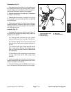
1. Support flex coupler (item 2) to prevent it from being
damaged during spring pin removal. Push spring pin
from flex coupler and bearing collar (item 23). Slide cou-
pler with hex shaft (item 3) from collar. Discard removed
spring pin.
2. Press ball bearing (item 28) from end of reel clutch
shaft. Discard removed bearing.
3. Carefully remove retaining ring (item 13) that se-
cures reel brake disc (item 14) to reel drive hub (item
18). Take care to not damage brake disc friction material
when removing retaining ring.
4. Remove reel brake disc (item 14) from reel drive hub
noting orientation of disc for assembly purposes. Fric-
tion material side of disc needs to be positioned toward
the reel brake ring (item 11) which is pressed into the
transmission housing.
5. Slide reel clutch hub (item 17) and reel clutch fork
(item 16) assembly from reel drive hub (item 18). Note
correct orientationof indicator mark on fork for assembly
purposes. If necessary, remove pivot pins (item 15) and
separate fork from hub.
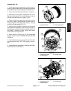
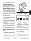
6. Use modified socket (see Special Tools in this chap-
ter) to remove bearing collar assembly from clutch shaf t
(Fig. 41).
IMPORTANT: To prevent damage, avoid using ex-
cessive clamping pressure on the reel clutch shaft
assembly.
A. Use flats on reel drive hub to carefully secure reel
clutch shaft assembly in a vise. Use a vise with soft
jaws to prevent damage to clutch shaft assembly
components.
B. Slide modified socket over bearing collar. Align
modified socket so that 5/32” pin can be inserted
through socket and hole in bearing collar.
C. Use modified socket and socket wrench to re-
move bearing collar assembly from clutch shaft.
1. Transmission housing
2. Flange bushing
3. Flange bushing
4. Reel brake ring
Figure 40
1
2
4
3
3
2
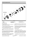
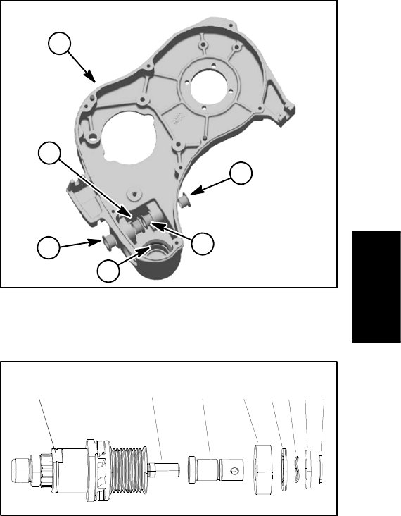
Figure 41
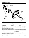
1. Retaining ring
2. Flat washer
3. Wave spring
4. Flocked bearing seal
5. Ball bearing
6. Bearing collar
7. Reel clutch shaft
8. Hub flat location
21345678
7. Remove retaining ring (item 27), flat washer (item
26), wave spring (item 25) and flocked bearing shield
(item 24) from bearing c ollar. Note orientation of flocked
shield for assembly purposes.
8. Press bearing (item 12) from bearing collar. Discard
removed bearing.
9. Slide reel clutch pulley assembly and reel drive hub
from clutch shaft.
10.If necessary, remove ball bearings and spacer from
pulley. Discard removed bearings.
Reel Clutch Shaft Assembly ( Fig. 39)
1. If ball bearings were removed from reel clutch pulley,
press new inner bearing fully to bottom of bore in pulley.
Install spacer into pulley and then press new outer bear-
ing into pulley until it contacts spacer.
2. If bearing was removed from bearing collar, press
new bearing fully onto collar.
Traction and Reel
Drive System