


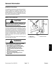

Greensmaster eFlex 1800/2100 GroomerPage 7 -- 11
7. Remove HOC nut (item 21), HOC washer (item 16)
and plow bolt (item 22) that secure RH groomer arm as-
sembly to drive plate assembly. Do not change height--
of--cut screw adjustment. Remove RH groomer arm
assembly from cutting unit.
8. Remove front roller assembly from cutting unit.
NOTE: To prevent grooming reel shaft from turning
when removing driven pulley, use wrench on shaft flats
to hold shaft.
9. Remove the lock nut (item 1) that secures driven
pulley (item 19) to grooming reel shaft. Remove driven
pulley from shaft.
NOTE: To prevent cutting reel from turning when re-
moving drive pulley, use a 1/2” socket on hex of reel
drive shaft that is used for backlapping the cutting reel.
10.Loosen and remove drive pulley (item 4) from the
cutting reel shaft.
11.Remove two (2) shoulder bolts (item 5) that secure
the groomer RH drive plate assembly (item 7) to the cut-
ting unit frame. Remove the RH drive plate assembly
from grooming shaft and cutting unit. Locate and re-
trieve groomer shim (item 8).
12.Carefully pull the grooming reel from the LH support
plate assembly (item 14).
13.Inspect seals, bushings and bearings in RH drive
plate, LH support plate and groomer arms for wear or
damage. Replace components as needed.
Installation (Fig. 8)
1. Apply a light coating of grease to ends of grooming
shaft and also to seal lips in RH drive and LH support
plates. Make sure that all bearings, bushings and seals
are properly installed.
2. Make sure that O--ring (item 25) is installed on
grooming reel shaft. Apply light coating of grease t o O--
ring.
3. Carefully place grooming r eel assembly into the LH
support plate taking care to not damage seal in support
plate or O--ring on shaft.
4. Apply light coating of grease to O--ring on RH drive
plate assembly pivot hub and pilot bore of cutting unit
side plate.
5. Position groomer shim (item 8) to RH drive plate as-
sembly.
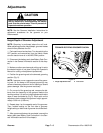
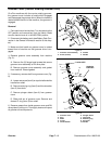
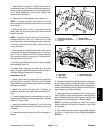
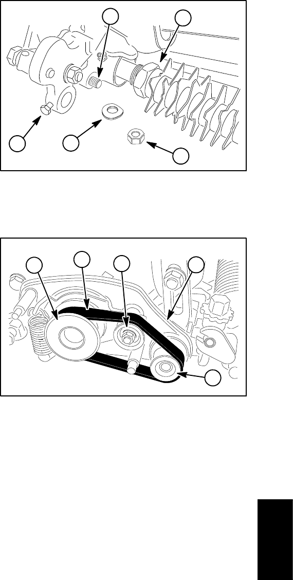
1. Front roller cap screw
2. Grooming reel assembly
3. Lock nut
4. Spring washer
5. Groomer arm lift rod
Figure 9
4
2
1
3
5
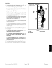
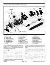
1. Drive pulley
2. Idler pulley
3. Driven pulley
4. RH drive plate assy
5. Groomer drive belt
Figure 10
1
2
4
3
5
6. Carefully place RH drive plate assembly onto groom-
er shaft taking care to not damage seals in drive plate.
Position drive plate to the cutting unit frame and secure
with two shoulderbolts (item 5). Makesure that RHdrive
plate rotates freely after installation.
7. Apply light coating of grease to hub on driven pulley
(item 19) taking care to not get grease on belt surface of
pulley. Slide driven pulley onto the grooming reel shaft
taking care to not damage seal in RH drive plate.
NOTE: To prevent grooming reel shaft from turning
when installing driven pulley, use wrench on shaft flats
to hold shaft.
8. Secure driven pulley to grooming reel shaft with lock
nut (item 1). Torque lock nut from 17 to 21 ft--lb (24 to
28 N--m).
Groomer