


Greensmaster eFlex 1800/2100 Page 4 -- 11 Electrical System
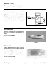
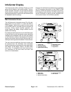
Electric Motor Rotor Tool Set
The rotor tool set for the electric motor is required to re-
move and install the rotor from the motor housing. The
tool set includes base plate, threaded shaft and handle
(Fig. 14).
Toro Part Number: TOR6028
NOTE: For electric motor service procedures, see
Electric Motor Service in the Service and Repairs sec-
tion of this chapter.
Rotor Removal
1. Remove gearbox cover and output gear from motor
assembly (see Electric Motor Service in the Service and
Repairs section of this chapter).
2. Remove screws that secure motor cover. Do not r e-
move cover from motor assembly.
3. Secure tool set base plate to motor housing with four
(4) of the cover screws.
4. Install threaded shaft into base plate.
IMPORTANT: The rotor magnets are very powerful
and can cause the rotorto shift position very rapidly
during removal. Becautiousduring rotorremovalto
prevent component damage or personal injury.
5. Turn threaded shaft with handle to remove rotor and
motor cover from motor housing. Support rotor to pre-
vent it from falling from housing during removal.
6. Leave threaded shaft installed in same position in
base plate for rotor installation purposes.
Rotor Installation
1. Secure tool set base plate to motor housing with four
(4) of the cover screws.
2. Make sure that threaded shaft is installed into base
plate so that the end of the threaded shaft prevents the
rotor body from entering the motor housing.
IMPORTANT: The rotor magnets are very powerful
and can cause the rotorto shift position very rapidly
during installation. Be cautious during rotor instal-
lation to preventcomponent damage orpersonal in-
jury.
3. While guiding rotor into motor housing, slowly rotate
threadedshafttoallowtherotortobedrawnintothe
housing. Once rotor is fully installed into housing, r e-
move tool set from motor housing.
Figure 14
1. Base plate
2. Threaded shaft
3. Handle
1
2
3
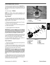
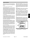
1. Screw (6 used)
2. Motor cover
3. O--ring
4. O--ring
5. Wave washer
6. Bearing
7. Rotor
8. Bearing
9. O--ring
10. Housing assembly
Figure 15
7
5
6
8
3
9
2
4
1
10
Electrical
System