


Greensmaster eFlex 1800/2100 Page 5 -- 15 Chassis and Controls
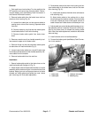
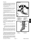
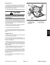
Removal (Fig. 14)
1. Parkmachineonlevelsurface.Turnkeyswitchtothe
OFF position and remove key from the switch. Discon-
nect the battery pack (see Battery Pack Connection in
the General Information section).
2. Pivot kickstand up and hold against the frame stops.
CAUTION
Be careful when removing or applying tension
from or to the torsion spring of the kickstand.
The spring is under heavy load and may cause
personal injury.
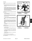
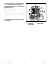
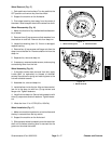
3. Use a nutdriver or small diameter pipe over the end
of the torsion spring. Push the torsion spring down and
in to release spring tension (Fig. 15).Slidetorsion spring
frompinonrearframe.
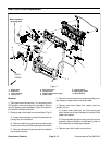
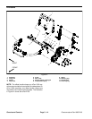
4. Remove cap screw, spacer and flange nut that se-
cure left side of kickstand to rear frame.
5. Remove kickstand from the machine.
6. If necessary, disassemble and remove service posi-
tion locking pin assembly (items 7, 8, 9 and 10) from rear
frame.
Installation (Fig. 14)
1. Make sure machine is parked on a level surface and
key is removed from key switch.
2. If service position locking pin assembly (items 7, 8,
9 and 10) was removed from rear frame, install removed
locking pin components.
3. Position kickstand inside the machine frame. Insert
cap screw (item 4) through the rear frame, kickstand and
spacer. Thread flange nut on cap screw and tighten to
secure kickstand.
4. Slidetorsion spring onto pin onrear frame. Place end
of spring in slotted hole in bottom of rear frame.
5. Pivot kickstand up and hold against the frame stops.
Use a nutdriver or small diameter pipe over the end of
the torsion spring. Push the spring end down and out to
install spring (Fig. 15).
6. Connectthe battery pack(see Battery Pack Connec-
tion in this section).
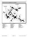
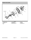
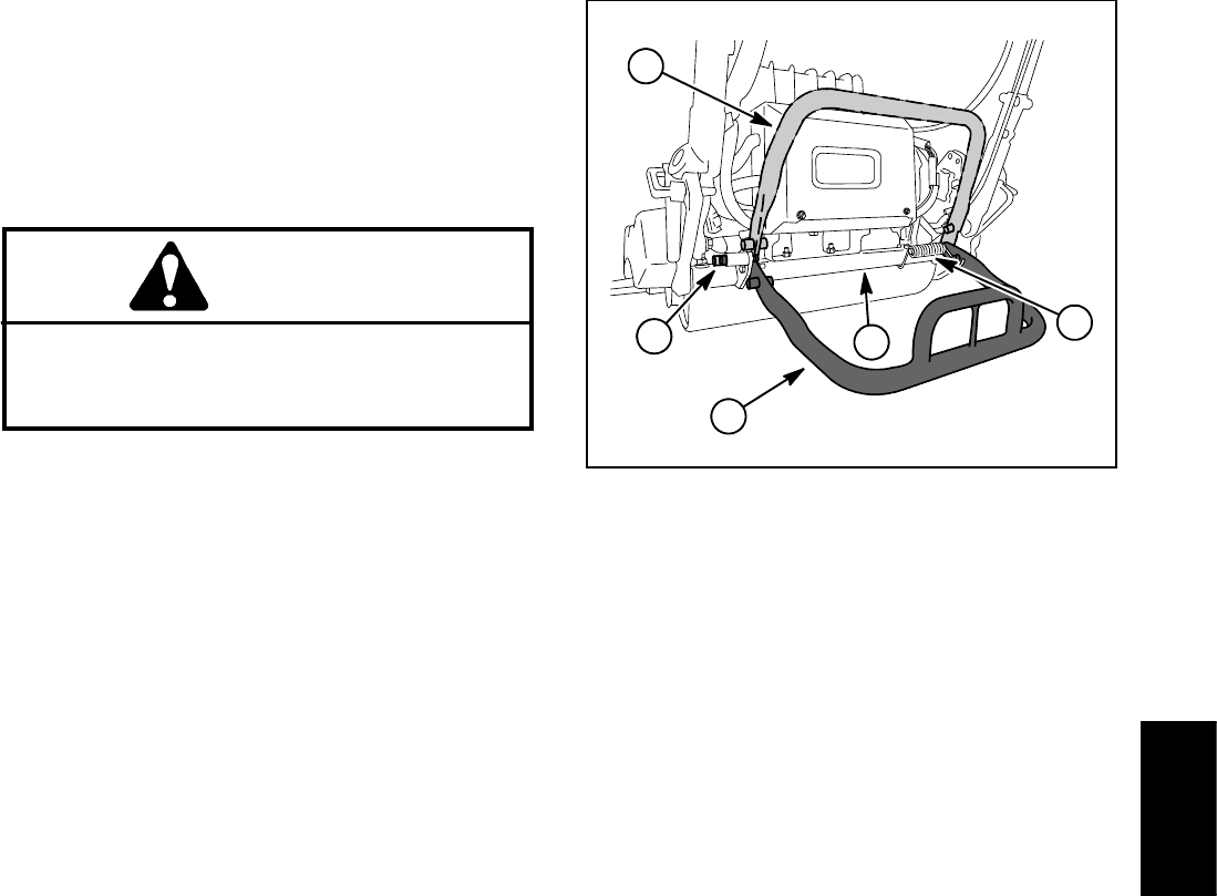
1. Kickstand (raised)
2. Kickstand (lowered)
3. Rear frame
4. Torsion spring
5. Service locking pin
Figure 15
1
4
3
2
5
Chassis and
Controls