


Greensmaster eFlex 1800/2100 Traction and Reel Drive SystemPage 3 -- 21
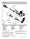
5. Separate LH side plate (item 25) from machine (Fig.
25):
A. Remove flange nut, hardened washer and car-
riagescrew(items3,4and6inFig.25)thatsecure
LH side plate to rear frame.
B. Remove three (3) flange screws and hardened
washers (items 8 and 4 in Fig. 25) that secure LH
side plate to frame.
C. Slide LH side plate from supporting bearing and
remove from machine.
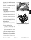
6. Insert bar stock or other suitable tool through spokes
of LH traction drum to keep drum from turning.
7. Whileretaining LH drum, loosen and remove bearing
nut (item 15) from traction drum assembly. The ball
bearing(item 14) is pressed onto the bearing nut so itwill
be removed with the nut.
8. Slide LH traction drum (item 13) from drum shaft. Lo-
cate and retrieve square key from shaft.
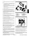
9. If necessary, carefully remove grease seal (item 12)
from LH traction drum taking care to not damage bore
of drum. Discard removed seal.
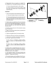
10.If necessary, remove LH hex shaft (item 16) and ball
bearing (item 14) from bearing nut.
11.Insert bar stock or other suitable tool through spokes
of RH traction drum to keep drum from turning.
12.Remove O--ring (item 30), pin (item 28) and lock col-
lar (item 27) from drum shaft.
13.While retaining remaining drum, loosen and remove
jam nut (item 11) from long spur gear.
14.Remove RH traction drum (item 10) from machine.
Locate and retrieve square key from spur gear.
NOTE: If removal of the drum shaft (item 7), long spur
gear (item 8) or differential assembly (Item 9) is neces-
sary, see Differential Assembly in this section.
Traction Drum Installation (Fig. 24)
1. Make sure that drum shaft (item 7), long spur gear
(item 8) and differential assembly (Item 9) are installed
to drum drive housing (refer to Differential Assembly in
this section).
2. Install LH hex shaft (item 16) and ball bearing (item
14) to bearing nut (item 15) if they were removed. Press
bearing fully onto bearing nut. Torque hex shaft from 70
to 80 ft--lb (95 to 108 N--m).
3. Place square key (item 6) into slot of long spur gear
(item 8). Apply antiseize lubricant to top surface of key.
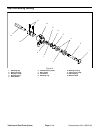
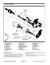
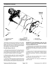
1. Kickstand
2. Rear frame
3. Flange nut
4. Hardened washer
5. Frame
6. Carriage screw
7. LH side plate
8. Flange screw (3 used)
9. Counterweight
10. Offset handle clamp
11. Handle clamp
Figure 25
6
8
9
10
1
11
4
3
5
7
2
4
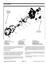
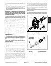
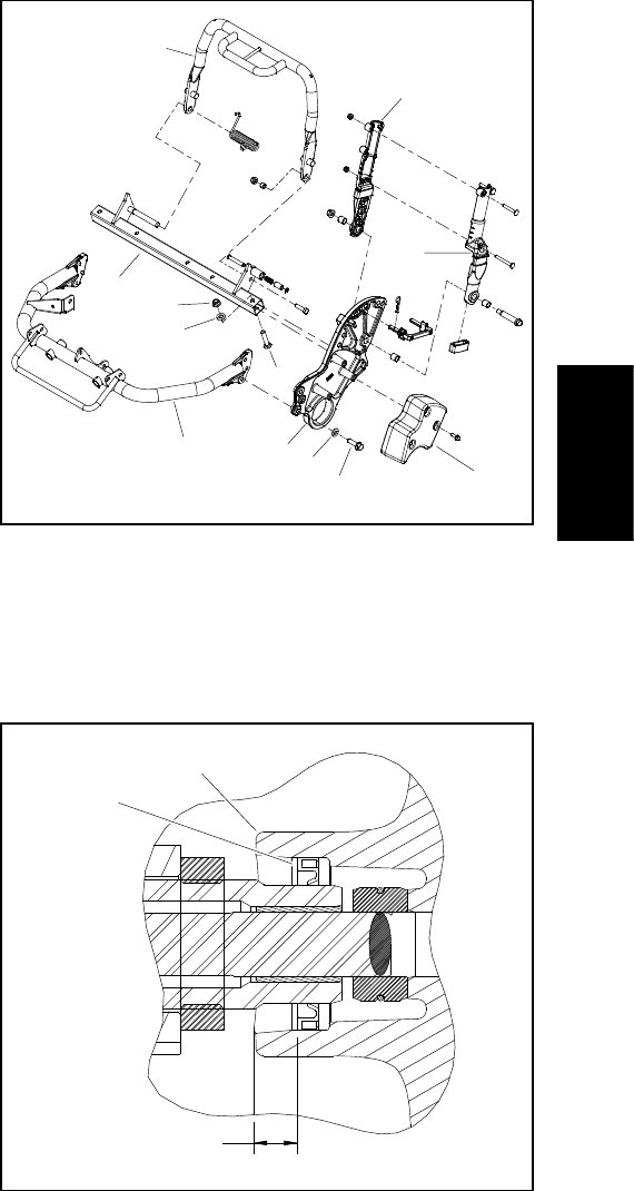
1. LH traction drum 2. Grease seal
Figure 26
2
1
0.470” to 0.530”
(12.0 to 13.4 mm)
4. Align slot in RH traction drum (item 10) with key on
long spur gear and slide traction drum onto gear.
5. Insert bar stock or other suitable tool through spokes
of RH traction drum to keep drum from turning.
6. Install jam nut (item 11) onto threads of long spur
gear to secure RH traction drum. Torque jam nut from
140 to 160 ft--lb (190 to 216 N--m).
Traction and Reel
Drive System