


Greensmaster eFlex 1800/2100 Page 5 -- 11 Chassis and Controls
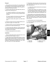
Disassembly
1. Parkmachineonlevelsurface.Turnkeyswitchtothe
OFF position and remove key from the switch. Discon-
nect the battery pack (see Battery Pack Connection in
the General Information section).
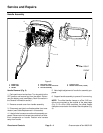
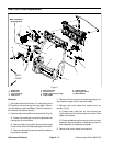
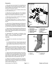
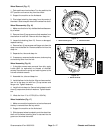
2. Remove console cover from handle to allow access
to lever a ssembly (Fig. 11).
3. Disconnect reel clutch cable from lever assembly
(see Reel Clutch Cable Replacement in this section).
Position end of cable away from lever assembly.
4. Disconnect wire harness connectors from traction
and reel engage switches (Fig. 11).
5. Disconnect spring (item 11 in Figure 11) that con-
nects operator presence control with traction lever as-
sembly.
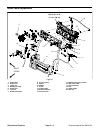
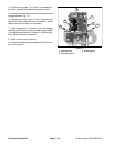
6. Remove four (4) flange head screws and flange nuts
that secure lever assembly and brackets to handle. Re-
move assembly (includinglever ass embly, shifter brack-
et, shift mount and switch mount bracket) from handle.
7. Remove two ( 2) flange head screws and flange nuts
that secure switch mount bracket and shift mount to
shifter bracket. Separate brackets to allow disassembly
of lever assembly.
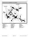
8. Disassemble lever assembly as necessary using
Figures 10 and 11 as guides. Note orientation of end
hooks on all springs for assembly purposes.
Assembly
1. Assemble lever assembly using Figures 10 and 11
as guides.
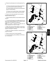
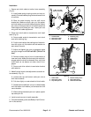
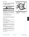
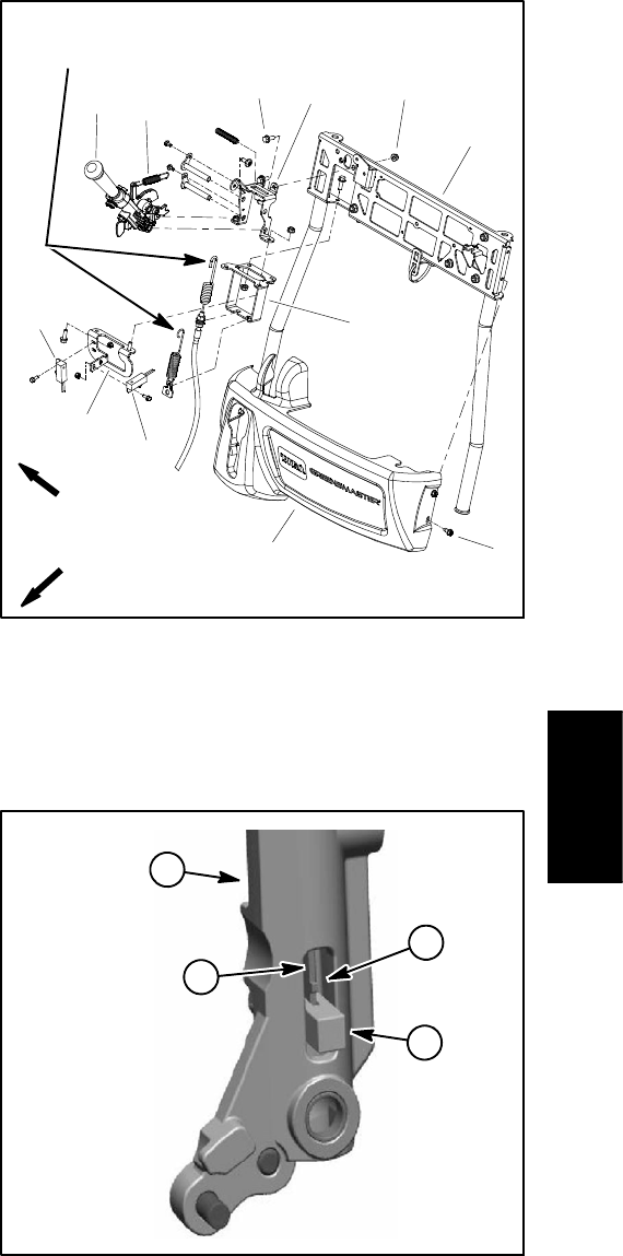
A. If shift arm link (item 4 in Figure 10) was removed
from transport lever, make sure that tab on shift arm
link is positioned toward solid end of latch pin (Fig.
12).
NOTE: One of the mounting holes in both the switch
mount bracket and shift mount is elongated to allow for
adjustment of clearance between transport lever (item
16 in Figure 10) and reel shift lever (item 17 in Figure
10).
2. Secureswitch mount bracket and shift mount toshift-
er bracket with two (2) flange head screws and flange
nuts. Before fully tightening fasteners, position legs of
shifter bracket to allow 0.040” (1.0 mm) clearance be-
tween transport lever and reel shift lever (Fig. 13).
3. Position lever assembly (including lever assembly,
shifter bracket, shift mount and switch mount bracket) to
handle. Secure assembly in place with four (4) flange
head screws and flange nuts.
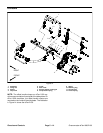
1. Traction switch
2. Traction lever assembly
3. Lower handle
4. Flange screw (4 used)
5. Flange nut (4 used)
6. Console cover
7. Screw (4 used)
8. Switch mount bracket
9. Shifter bracket
10. Shift mount
11. Spring
12. Reel engage switch
Figure 11
FRONT
RIGHT
5
3
1
2
6
4
7
8
10
9
11
12
Note orientation
of spring hooks
1. Latch pin
2. Shift arm link
3. Transport lever
4. Shift link tab
Figure 12
1
2
4
3
Chassis and
Controls