


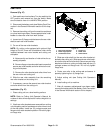
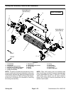

Greensmaster eFlex 1800/2100 Page 6 -- 27 Cutting Unit
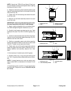
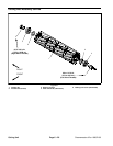
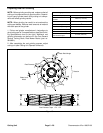
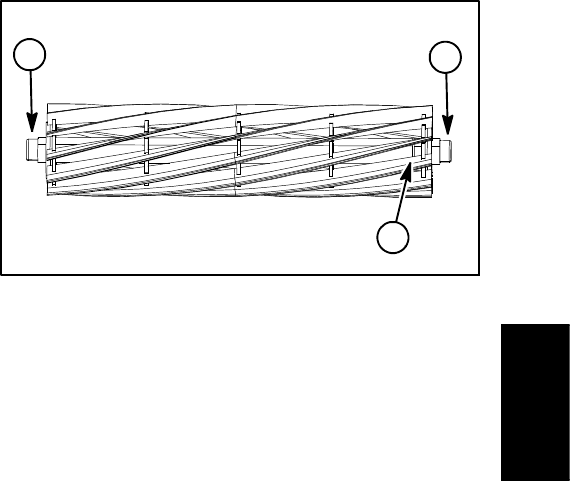
Disassembly of Cutting Reel (Fig. 37)
IMPORTANT: When removing reel drive shaft (item
4), use appropriate wrench or socket on 1” hex sur-
face of shaft. Do not use 1/2” extension on end of
reel drive shaft when loosening or tightening drive
shaft. The 1/2” hex is intended for backlapping only.
1. Remove bearing lock screw (item 5) and reel drive
shaft (item 4) from cutting reel. Reel drive shaft has LH
threadsand is in end ofreelshaft identified with a groove
that is just inside of reel spider (Fig. 38).
2. Slide bearings from reel shaft.
3. Note orientation of flocked seals for assembly pur-
poses. Remove seals from reel shaft.
Inspection of Cutting Reel (Fig. 37)
1. Inspect reel bearings to insure that they spin freely
and have minimal axial play.
2. Inspectthe reel shaft as follows. Ifreel damage is de-
tected, replace cutting reel.
A. Check the reel shaft for bending and distortion by
placing the shaft ends in V--blocks.
B. Check the reel blades for bending or cracking.
C. Check the service limit of the reel diameter (see
Preparing a Reel for Grinding in this section).
D. Check threads in ends of reel shaft.
3. Check the woodruff key slot and hex drive on the reel
drive shaft (item 4) for excessive wear or distortion. Re-
place drive shaft if damage is evident.
Assembly of Cutting Reel (Fig. 37)
1. If bearings and/or flocked seals were removed from
reel shaft, discard removed components and r eplace.
IMPORTANT: The flocked seal should be installed
so the flocked side of the seal is toward the bearing
location.
2. Press flocked seals onto reel shaft with flocked side
orientated toward bearing location. Seal should be per-
pendicular to reel shaft after installation.
3. Slide bearings fully onto reel shaft. Bearings should
bottom on reel shaft shoulder.
IMPORTANT: When installing reel drive shaft (item
4), use appropriate wrench or socket on 1” hex sur-
face of shaft. Do not use 1/2” extension on end of
reel drive shaft when loosening or tightening drive
shaft. The 1/2” hex is intended for backlapping only.
4. Installbearinglock screw (item 5)andreel drive shaft
(item 4) into reel shaft to secure bearings. Reel drive
shaft has LH threads and should be installed in end of
reelshaftidentifiedwithagroove thatis just inside ofreel
spider (Fig. 38).
NOTE: Installation torque for bearing lock screw and
reel drive shaftis from 90 to 110 ft--lb (123 to 149 N--m).
It is easiest to torque these items after the cutting reel is
installed in the cutting unit frame (see Reel Assembly
Removal and Installation in this section).
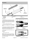
1. LH threads
2. Groove
3. RH threads
Figure 38
1
2
3
Cutting Unit