


Greensmaster eFlex 1800/2100Groomer Page 7 -- 18
Grooming Reel Bearing Replacement
Bearing Removal
1. Parkmachineon level surface. Turnkeyswitch to the
OFF position and remove key from the switch. Make
sure the traction lever is in the NEUTRAL position. En-
gage parking brake.
2. Disconnect the battery pack (see Battery Pack Con-
nection in the General Information section of this chap-
ter).
3. Remove the cutting unit from the machine and place
cutting unit on a flat work area.
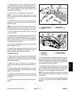
4. To remove groomer drive plate assembly from right
side of cutting unit, remove front roller, grooming reel
and then drive plate assembly (see Grooming Reel (For-
ward Rotating or Counter Rotating) in this section).
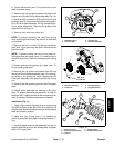
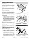
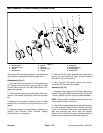
5. To remove support plate assembly from left side of
cutting unit (Fig. 19):
A. Remove reel drive cover, drive belt, reel pulley
and then reel drive assembly from cutting unit (see
Reel Drive Assembly inthe Service and Repairssec-
tion of Chapter 3 -- Traction and Reel Drive System).
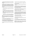
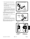
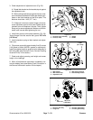
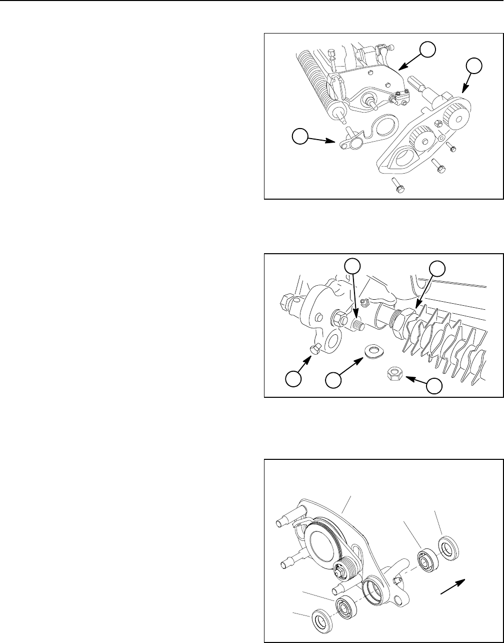
B. Remove lock nut and spring washer that secure
LH groomer arm lift rod to support plate(Fig. 20). Re-
move support plate from cutting unit.
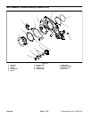
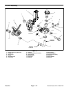
6. Remove grooming reel seals and bearings from RH
drive plate and LH support plate assemblies (Figs. 21,
22 and 23). Discard all r emoved seals and bearings.
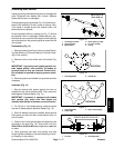
Bearing Installation
1. Install new grooming reel bearings andseals into RH
drive plate and LH support plate assemblies ( Fig. 24):
IMPORTANT: Bearings should be installed with ex-
tended inner races toward center of housing. Also,
apply pressure equally to inner and outer bearing
races when installing bearings.
A. Press new outer bearing fully to shoulder of RH
drive plate bore. Then, install new inner bearing until
inner race contacts outer bearing race.
B. Press new bearing into LH support plate until it is
flush with shoulder of bearing bore.
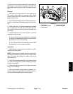
C. Install new seals into groomer sideplates.NOTE:
Seals should be installed so the lip side of the seal
will face the center of the cutting reel. When bearings
are greased, grease will purge from inner seals.
1. Cutting unit
2. Reel drive assembly
3. LH support plate
Figure 19
1
3
2
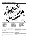
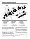
1. Front roller cap screw
2. Grooming reel assembly
3. Lock nut
4. Spring washer
5. Groomer arm lift rod
Figure 20
4
2
1
3
5
1. RH drive plate assy
2. Bearing (2 used)
3. Seal (2 used)
Figure 21
Seal lips
(toward center of
cutting unit)
3
2
2
3
1
FORWARD ROTATING GROOMER