


Greensmaster eFlex 1800/2100 Traction and Reel Drive SystemPage 3 -- 37
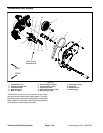
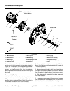
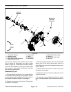
6. As necessary, remove components from driven
pulley (item 8):
A. Remove retaining ring(item 13),flat washer (item
12), wave spring (item 11) andflocked bearing shield
(item 10) from driven pulley. Note orientation of
flocked shield for assembly purposes.
B. Press bearings (items 4 and 9) from pulley. Dis-
card removed bearings.
C. Remove retaining ring (item 5) and slide splined
coupler (item 6) from pulley. Clean splined coupler
and inspect coupler for wear or damage.
D. Inspect the drive spline (item 7) that is attached to
driven pulley. Drive spline should be free of bending,
distortion or other damage.
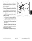
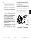
7. Ifdrive spline (item 7) needs to beremovedfromdriv-
en pulley, use the following procedure:
IMPORTANT: Avoid using excessive clamping
pressure on the driven pulley flats to prevent dam -
age to pulley.
A. Use flats on driven pulley to carefully secure
pulleyinavise.Useavisewithsoftjawstoprevent
pulley damage.
B. Remove set screw (item 14) from end of pulley.
C. Slide coupler (item 6) onto drive spline and use
spline insert tool (seeSpecialTools in this chapter) to
remove drive spline from driven pulley.
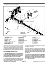
Assembly (Fig. 44)
1. If d rive spline (item 7) was removed from driven
pulley, secure drive spline to pulley:
IMPORTANT: Avoid using excessive clamping
pressure on the driven pulley flats to prevent dam -
age to pulley.
A. Use flats on driven pulley to carefully secure
pulleyinavise.Useavisewithsoftjawstoprevent
pulley damage.
B. Drive spline should either be replaced (new drive
spline has patchlock on threads) or have Loctite
#242 (or equivalent) applied to threads before instal-
lation.
C. Slide coupler (item 6) onto drive spline and use
spline insert tool (seeSpecialTools in this chapter) to
secure drive spline into driven pulley.
D. Install set screw (item 14) into end of pulley and
tighten against drive spline.
E. Secure coupler (item 6) in driven pulley with re-
taining ring (item 5).
2. Install all removed components onto driven pulley
(item 8).
A. If bearings (items 4 and 9) were removed from
driven pulley, press new bearings onto pulley.
B. As required, install flocked bearing shield (item
10) (flocked side orientated toward bearing location),
wave spring (item 11) and flat washer (item 12) onto
driven pulley. Secure components with retaining ring
(item 13).
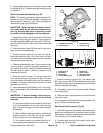
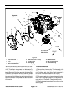
3. If motor adapter (item 1) was removed from trans-
mission housing, secure adapter to housing with four (4)
washer headscrews (item 2). Tightenscrews asfollows:
A. First, using an alternating crossing pattern,
torque all screws from 15 to 40 in--lb (1.7 to 4.5
N--m).
B. Again using an alternating crossing pattern,
torque all screws from 85 to 95 in--lb (9.6 to 10.7
N--m).
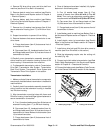
4. Slide driven pulley assembly (including bearings)
into motor adapter.
5. Install transmission drive belt and all machine com-
ponents removed for reel drive system service (see
Transmission Drive Belt in this section).
6. Fill internal spline area of splined coupler (item 6)
with high temperature Mobil XHP--222 grease (or equiv-
alent).
7. Install electric motor to transmission (see Electric
Motor in the Service and Repairs section of Chapter 4
-- Electrical System).
8. Connectthe battery pack(see Battery Pack Connec-
tion in the General Information section of this chapter).
Traction and Reel
Drive System