


Greensmaster eFlex 1800/2100 Traction and Reel Drive SystemPage 3 -- 17
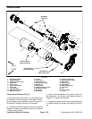
6. Remove retaining ring (item 6) that secures brake
band to brake clevis pin. Slide brake band from brake
clevis and brake mount pins and remove band from
drum drive housing.
7. Carefully remove one end of extension spring (item
9) from anchor point and rotate spring away from drive
belt.
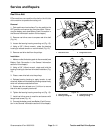
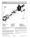
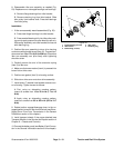
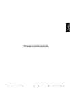
8. Pivot the idler pulley away from the drum drive belt
to loosen belt tension (Fig. 21).
9. Remove drum drive belt from drive pulley and then
from differential pulley.
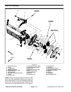
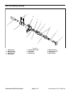
Installation (Fig. 19)
1. Make sure that the battery pack is disconnected (see
Battery Pack Connection in the General Information
section of this chapter).
2. Placedrumdrivebeltonto differentialpulley andthen
fit belt to drive pulley. Make sure that belt is on rear side
of idler pulley.
3. Carefully install removed end of extension spring
(item 9) to anchor point.
4. Install brake band over brake surface of differential
pulley. Slide ends of brake band onto brake clevis and
brake mount pins. Secure brake band to brake clevis pin
with retaining ring (item 6).
5. Make sure that wave washer (item 4) is pressed into
bore of drum drive cover.
6. Position new gasket (item 3) to housing surface.
7. Slide drum drive cover onto drum drive assembly.
8. Install seven (7) washer head screws to secure cov-
er to housing. Tighten screws as follows:
A. First, using an alternating crossing pattern,
torque all screws from 15 to 40 in--lb (1.7 to 4.5
N--m).
B. Again using an alternating crossing pattern,
torque all screws from 85 to 95 in--lb (9.6 to 10.7
N--m).
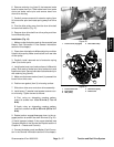
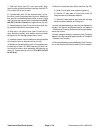
9. Rotate traction engage/disengage lever to the en-
gaged position to tension the drum drive belt (Fig. 20).
10.Install transport wheels if they were attached (see
Transport Wheels in the Service and Repairs section of
Chapter 6 -- Chassis and Controls).
11.Connect thebattery pack (see Battery PackConnec-
tion in the General Information section of this chapter).
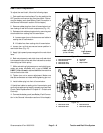
Figure 20
1. Traction lever (engaged) 2. RH handle clamp
2
1
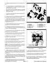
1. Traction drive belt
2. Drive pulley
3. Idler pulley
4. Differential pulley
5. Brake band
Figure 21
2
1
4
3
5
Traction and Reel
Drive System