


Greensmaster eFlex 1800/2100Traction and Reel Drive System Page 3 -- 26
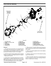
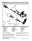
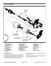
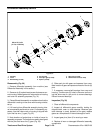
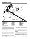
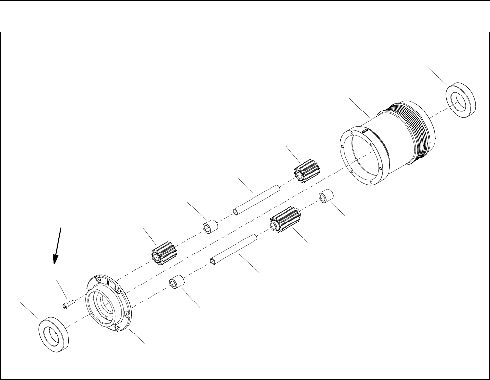
Differential Assembly Service
1. Housing
2. Cover
3. Ball bearing (2 used)
4. Pin (6 used)
5. Dual spur gear (6 used)
6. Spacer (9 used)
7. Spur gear (3 used)
8. Socket head screw (6 used)
Figure 30
2
3
6
8
1
5
7
4
4
6
5
6
3
99 to 121 in--lb
(11.2 to 13.6 N--m)
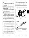
Disassembly (Fig. 30)
1. Remove differential assembly from machine (see
Differential Assembly in this section).
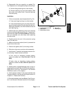
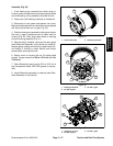
2. Remove six (6) socket head screws that secure cov-
er to housing. Note alignmentof index marks onhousing
and cover for assembly purposes (Fig. 31).
3. Place differential assembly on workbench so that the
differential is resting on the cover with housing orientat-
ed up.
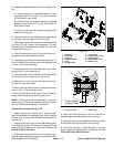
4. Lift housing from differential assembly leaving inter-
nal components positioned on cover. For assembly pur-
poses, note that index mark on housing is aligned with
a pin that has one (1) gear (Fig. 32).
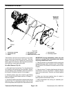
5. Note locations of projections on inside of cover for
assembly purposes. The projections need to be aligned
with the pins that have one (1) gear (Fig. 33).
6. Slide each pin with gears and spacers from cover.
Note location of gears and spacers on each of the six (6)
pins.
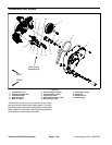
7. If necessary, remove ball bearings from cover and
housing. There are two (2) holes in the cover and hous-
ing that allow use of a pin punch to remove bearings.
Discard removed bearings.
Inspection (Fig. 30)
1. Clean all differential components.
2. Inspect all differential gears carefully looking for
chipped teeth, wear or other damage. Because gear
tooth damage is rarely isolated to one gear, replace
gears as a complete set if internal damage is found.
3. Inspect gear pins (item 4) for scoring or wear.
4. Replace all worn or damaged differential assembly
components.